Part Modeling with Equation Driven Curves
advertisement
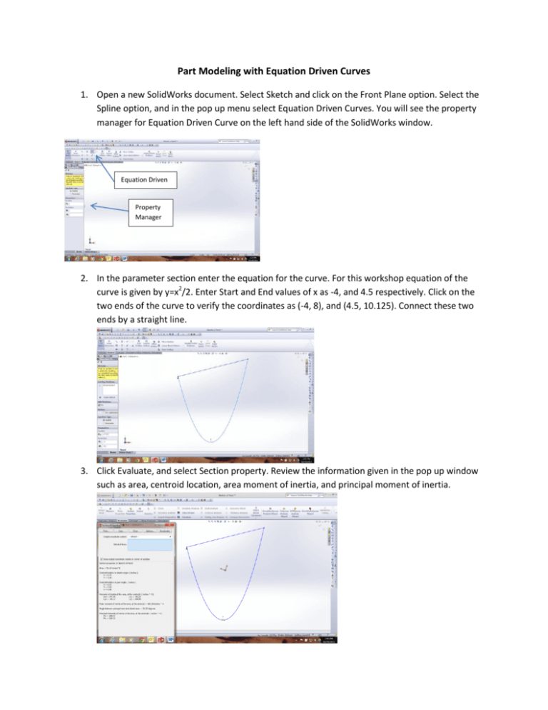
Part Modeling with Equation Driven Curves 1. Open a new SolidWorks document. Select Sketch and click on the Front Plane option. Select the Spline option, and in the pop up menu select Equation Driven Curves. You will see the property manager for Equation Driven Curve on the left hand side of the SolidWorks window. Equation Driven Property Manager 2. In the parameter section enter the equation for the curve. For this workshop equation of the curve is given by y=x2/2. Enter Start and End values of x as -4, and 4.5 respectively. Click on the two ends of the curve to verify the coordinates as (-4, 8), and (4.5, 10.125). Connect these two ends by a straight line. 3. Click Evaluate, and select Section property. Review the information given in the pop up window such as area, centroid location, area moment of inertia, and principal moment of inertia. 4. Click on Features and select Extrude Boss/Base option. Extrude the plate 0.25 inch to create a solid model of the plate. In the View Orientation select Isometric view. 5. Right click on Material in the Feature Tree menu and select Edit Material option. In the Material menu first select Plastic and then ABS as shown in the following figure. 6. One more time click on Evaluate and this time select the Mass Properties option. Review the information in the Mass Properties window such as volume, mass, and mass moment of inertias.
