A Solar Water Heater System (Passive)
advertisement
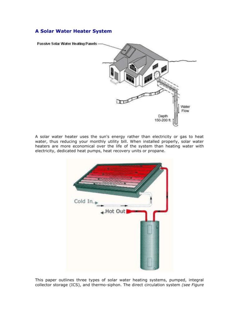
A Solar Water Heater System A solar water heater uses the sun's energy rather than electricity or gas to heat water, thus reducing your monthly utility bill. When installed properly, solar water heaters are more economical over the life of the system than heating water with electricity, dedicated heat pumps, heat recovery units or propane. This paper outlines three types of solar water heating systems, pumped, integral collector storage (ICS), and thermo-siphon. The direct circulation system (see Figure 1, page 2) circulates potable water from the water storage tank through one or more collectors and back into the tank. The solar collector is the main component of the solar system. It is usually a metal box with insulation and a black absorber plate that collects solar radiation and heats the water. The circulating pump is regulated by either an electronic controller, a common appliance timer, or a photovoltaic (PV) panel. In integral collector storage systems, the solar water storage system is built into the collector. The potable water in the collector unit is heated by the sun and delivered by city or well water pressure to an auxiliary tank (which contains non-solar back-up heating) or directly to the point of use. A thermo-siphon solar water heating system has a tank mounted above the collector (normally on the roof) to provide a natural gravity flow of water. Hot water rises through piping in the collector, which is mounted below the tank; heavier cold water sinks to the lowest point in the system (the collector), displacing the lighter hot water which rises to the tank. The ICS and thermo-siphon systems are simple since they use no pumps or controllers and water always flows through the collector. As sunshine strikes the collector, the water inside it is heated. If the circulating pump is regulated by a PV panel, the pump starts turning as the PV panel is activated by the same sunshine. This direct current (DC) motor pump moves water from the tank through the collector and back to the tank. As the sun's intensity changes throughout the day, the circulating pump also changes its speed accordingly. By the end of the day, the water in the tank has been circulated many times through the collector and has been heated to usable hot water temperatures. If the circulating pump is regulated by an electronic differential controller, a sensor at the outlet of the collector and a sensor at the bottom of the tank (Figure 1) activate the circulating pump when the water in the collector is about 15-200 F warmer than the water at the bottom of the tank. The pump then circulates water from the collector and the tank. This process continues as long as the water temperature at the collector outlet is about 5 0 F higher than that in the bottom of the tank. If the temperature difference decreases further, the controller automatically shuts off the pump. Common appliance timers also may control system operation. The timer is set to operate during a period of the day when solar radiation is available to heat the potable water. It is important that the timers used in these systems incorporate battery back-up in the event of power failures. In order to avoid loss of energy from the tank during overcast days, the collector feed and return lines are both connected at the bottom of the storage tank. During normal operation, natural stratification allows the warmer water to rise to the top part of the tank. During periods of insufficient sunshine or high hot water demand, a backup electrical element in the storage tank heats the water. The check valve prevents heat loss when the circulating pump is off. The circulating pump consumes only a small amount of electricity — around $5 to $10 worth per year, or in the case of PV — none. Figure 1. A solar water heating system Freeze protection is an absolute must for any solar system because a single freeze can destroy a collector. Even in Miami, collector tubes have frozen and burst during hard winter freezes. In order to avoid problems, Florida Solar Energy Center standards require that all solar systems be designed and installed with two freeze protection methods. The strategies and any instructions for the homeowner should be posted on a label affixed to a prominent location on the solar system, (usually the storage tank). There are a number of options available to prevent freeze damage to solar systems. In the south and central Florida areas, flush-type freeze prevention valves are being used. These valves open when the air temperature approaches freezing. Water pressure forces water from the storage tank through the collectors and out through the valve. The valve closes when the water leaving the valve reaches 50 0 F. This process prevents the water in the collector tubes from freezing and rupturing the tubes. Though water is purged from the system and lost, only a few gallons are needed to protect the collector from freezing. Another method of freeze protection is achieved by water recirculation. When the temperature drops below 40 0 F, a collector freeze sensor activates the pump to circulate warm water through the collectors. A second level of protection in this system, in the event of power failures, is provided by drain valves that manually drain the collector. Manual protection alone may be adequate for conscientious homeowners in southern Florida areas where hard freezes are rare. It is best to review the manual draindown instructions provided on the freeze information label or call your installer prior to manually draining your system. ICS systems incorporate thermal mass freeze protection. The large size of the tanks in the ICS units requires a much longer and more severe period of freeze temperatures before all the water in the tubes freezes. Florida freezes are generally not severe enough to turn all the water in ICS tanks into ice. Nevertheless, piping on the roof and in attics must also be protected. ICS systems in central and north Florida also incorporate a freeze prevention valve as a secondary freeze protection mechanism. An indirect system is shown (Figure 3). An antifreeze solution, similar to that used in automobiles, is circulated through the collector. A heat exchanger between the collector and storage tank transfers heat from the antifreeze to the potable water. Although this system is usually more expensive and less efficient than direct systems (in which the water used for bathing, etc., is the same water circulated through the collectors), it provides better automatic freeze protection in colder climates. In some cases, thermo-siphon systems also incorporate a heat exchanger in their design, which makes the thermo-siphon design quite suitable for colder climates. Two other types of freeze protection methods —automatic drain-down and drainback systems — are used extensively in the northern United States and are also suitable for north and central Florida. Drain-down systems normally use electrically operated valves that automatically drain the water from the collector during freezing temperatures. In drain-back systems, the collector is automatically drained whenever the circulating pump stops. With careful design and installation, both drain-down and drain-back systems can be fail-safe and cost effective. Figure 3. Indirect pumped system using antifreeze solution There are basically two types of solar collectors available for solar water heating. The first is referred to as a flat-plate glazed solar collector. The second is the integral collector storage (ICS) collector (Figure 2). Both collectors are mounted in a fixed position throughout the year and do not track the sun as do some collectors that are used primarily for high-temperature applications. A basic flat-plate collector consists of a metal enclosure, an absorber plate and flow tubes, insulation, and a glass covering. Flat-plate collectors can be 2 to 4 feet wide, 5 to 12 feet long, and 4 inches thick. The absorber takes in the sun's energy, which is then transferred to the water flowing through the tubes attached to the absorber. An ICS collector consists of large tubes, often 4 inches in diameter, in which potable water is both heated and stored in a combined heat storage and collection unit. As with the flat-plate collector, the ICS unit also consists of a metal enclosure, insulation, and a glass covering. ICS units are available in sizes ranging from 30 to 50 gallons, and can range from 4 feet in width to 8 feet in length to 10 inches in depth. Figure 2. ICS collector To reduce heat losses, all flat-plate and ICS collectors generally have insulation behind the absorber plate and a glass cover on the front, facing the sun. The best cover material is tempered glass of low iron content. Some edge insulation inside the enclosure box is also necessary. The absorber plate is made of copper and is coated with a black chrome or nickel material called a selective surface. This surface greatly enhances the collector's ability to capture and retain solar energy. Some manufacturers also use black paint as an absorber coating. A document entitled Thermal Performance Ratings, available from the FSEC Public Information office, contains the performance rating for each solar collector certified by the Center. The document also provides an approximate efficiency-per-dollar comparison method you can use as a guide for rejecting inefficient or overly expensive collectors.
