Carb Stripping Draft..
advertisement

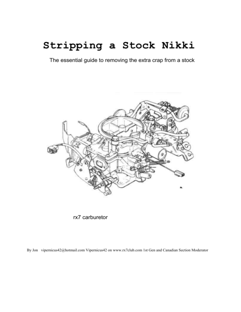
Stripping a Stock Nikki The essential guide to removing the extra crap from a stock rx7 carburetor By Jon vipernicus42@hotmail.com Vipernicus42 on www.rx7club.com 1st Gen and Canadian Section Moderator Note: Carb pictured above is for artistic representation only and does not reflect the carb used in this tutorial INDEX On Carburetor: 1. Introduction 2. #2 Anti-Afterburn Valve 3. Throttle Opener for A/C 4. Throttle Position Sensor 5. Solonoid on Vac Secondary Diaphragm box 6. Small Front-Side Choke Diaphragm and Components 7. Dashpot 8. Rear-Side Choke Components 9. Choke Assembly Bracket 10. Choke Butterfly 11. Choke Rod Optionals • Altitude Compensator • Vent Solonoid On Intake Manifold: I. Air Control Valve and Stud II. Block Off Plate III. AAB Valve Vacuum Source IV. Shutter Valve V. Shutter Valve Butterfly Other: • 20mm Freeze Plugs Introduct ion Hey All, Welcome to Jon’s guide to removing the extra crap from your stock carburetor. Before you ask, no it will not pass emissions anymore if you follow this guide, especially if you’re also removing the rat’s nest and air pump (which you might as well if you’re doing this already). Disclaimer: Any modifications you feel you are prompted to make as a result of reading this article are your own responsibility. I will not be held liable for any damage caused to you or your vehicle as a result of your actions. How This Tutorial Works: Steps 1 to 11 can be done easily and with little risk or serious modification, and are reversible. The “optional” steps require a bit more work, but can be left alone if desired. Steps I-V require a bit of simple fab work that anyone can easily do and are highly recommended. I would do steps 1-11 first, then test it. Then do I-V (and the Freeze Plug), and test it. And finally, give the optionals a try if you’re really adventurous. Anti-Afterburn Valve First on the chopping block is the Anti Afterburn Valve. The apparent reason for the AAB Valve is to help prevent “afterburning” or backfiring under certain conditions. Amazingly enough, after this entire tutorial is done, I have yet to have a single backfire, even with my RB “long primary” exhaust system. Even my Sterling doesn’t backfire, so my guess is that it’s meant to correct for a situation where things aren’t running right. If you’re not backfiring now, you probably won’t be after this mod. This is the anti-afterburn valve It’s held in place by two 10mm bolts and four hoses. Remove the bolts, disconnect the far end of the hoses, and block off the ports the two small hoses connected to with vacuum caps. Throttle Opener Next up, throttle opener. This widget is a vacuum-controlled hook which pull back on the throttle linkage when your A/C is on. What’s crazy is that this thing appeared on pretty much all stock Nikkis that I’ve seen, whether or not your car was equipped with A/C. If you do have A/C, then you might want to tune your idle up 100rpm or so to compensate, otherwise, chuck it. This is the throttle opener (the black mushroom-topped thing with a hose sticking out) It’s held in place by two 10mm bolts which also have a Phillips screw head. A 10mm socket works best on these. Remove the two bolts, and chuck the part into the pile of junk. Throttle Position Sensor Why there’s a Throttle Position Sensor on a carbureted car I’m not entirely sure. My best guess is that the signal from this sensor has some bearing on whether some of the solenoids in the rat’s nest are “opened” or “closed” at a given time. But you’ve already removed your rat’s nest, haven’t you? Older carbs, aftermarket carbs, and many stripped nikkis have done without this sensor, so off it goes. This it the TPS. It’s held in place by two 10mm bolts. Remove bolts, remove sensor. It’s that easy. Another addition to the junk pile. Solenoid There’s a solenoid bolted to the side of the Vacuum Secondary box. This is an ‘84-’85 specific thing which unfortunately doesn’t show up in the Mazda carb manual or carb training manual. Thankfully, its purpose seems to be as useful as your appendix, so it gets removed with about the same amount of consequence. Here’s the solenoid. It’s held in place with two Phillips screws. Note: “Liquid Wrench” is your friend, these screws are extremely easy to strip, and you need to put them back Remove screws, remove the solenoid, replace the screws. Follow the tubes to their endpoints and cap them with vacuum caps. Another addition to the junk pile. Front Choke Assembly Contrary to popular belief, you don’t actually need the majority of the choke assembly to be able to cold start. Unless it drops down below 10 degrees Celsius in your area (the coldest I can verify that I’ve driven my car in without a choke), you don’t need anything but the fast-idle rod. So we will remove the choke assembly starting with the front pieces The front choke assembly is held on with two Phillips screws. Remember to soak them for a few minutes in Liquid Wrench or the penetrating oil of your choice before removing to prevent from striping them. Here are the screws removed. Note which one is the long one and which is the short one. The long one must be reinstalled, the short one can be left off. Trace back the hose and remove it, the “T” valve and the other short length, and cap the source. You probably have a vacuum cap you put on the “T” in an earlier step, retrieve it, then junk this bugger. Dashpot Before we remove the rest of the choke assembly, the dashpot has to get out of the way so we can get to one of the screws. We were going to remove the dashpot anyway, so now’s a good time. It’s purpose in life is to stop the throttle from snapping shut immediately if you completely let off the gas. It gently closes the throttle butterflies for you. Since you can do this with your foot, we don’t need the dashpot. Just use a little more fineness, rather than being abrupt with your pedal movements. You can see how the dashpot works by working the throttle linkage and watching the little white plastic piece move. Or we could just remove the bulky thing. There’s one bolt on the top of the dash-pot which must be removed, then turn the entire dashpot counter-clockwise (or if you’re in the UK, “anti-clockwise”), to unscrew it from it’s spot. Out it comes, giving you much better access to the throttle linkage if ever you’re standing by the passenger side of the car and want to reach down and rev the car by hand instead of getting a friend on the gas pedal. Rear Choke Assembly For those of you still wondering, your actual choke knob is controlled by a temperature sensor on the back of the water pump, so it will still work without these pieces. And without these pieces there will still be something for the choke knob wire to attach to, which indeed will rev the car up to 2k rpm when you pull the knob out. So your “choke” will still work almost exactly TM the same without all this stuff, it just might not work in Canadian Winter but you shouldn’t be driving your seven in temps below 10C anyway. I know it’s the same picture as I used for the dashpot, but you can see both clearly here. The choke assembly is just above the dashpot. It’s held in place with three Phillips screws. Again, don’t forget your liquid wrench, I can’t emphasize enough how much it sucks to strip these things. Follow the clear tube back to its source and block it off with a vacuum cap. Da da dum dum dum… another one bites the dust! (if this reference eludes you, your car is probably older than you are. Go buy some “Queen” CDs or MP3s) Choke Assembly Bracket Now that the choke components are out of the way, we can get the bracket out of there. You’ll need some patience for this, because it’s sandwiched between the bracket that holds your primary and secondary throttle return springs, and the body of the carb. You need to unscrew that bracket, and hold it in place while sliding the choke assembly bracket out. It takes some fineness, and a friend’s helping hand doesn’t hurt, but it can be done alone. Pay close attention to the throttle return springs in this picture. Yours should still look like that after. If they don’t look *exactly* like that (with the top spring having it’s rod extend upwards to that lever) then make sure you fix it. That rod allows your secondaries to open, it needs to be in the right spot. Three Phillips screws, two on top, one on the side, hold the throttle return spring bracket in place, sandwiching the choke assembly bracket underneath. Remove the screws while holding that bracket, slide the choke assembly bracket out, and put the screws back. Remember where the big screw goes. It must return to the same place. As a note, it’s easier to get to the side screw if you unbolt the Altitude compensator (see pg 14) even if you are leaving it on the carb. Choke Butterfly The choke butterfly closes (with the help of all the already-removed choke pieces) so that less air flows through the carb during the warm up process. Less air means a richer mixture, which helps it run when cold. I’ve never seen a huge difference between having this present and just using the fast idle, so off it comes. Two tiny Phillips screws hold it to the rod. Don’t go dropping the screws into the carb, though if the carb is sitting on your workbench, you can most probably just let them fall through. Another one for the pile. Choke Rod The last part of the whole choke assembly is the rod. I’ll warn you that the rod is not always easy to remove because often dirt and/or corrosion has built up on either side of it, making it too large to easily slide through the holes in the air horn. The rod is also easy to bend to the point where it breaks. Since I knew I wouldn’t need it, this was my chosen method of removal this time, but I’ve successfully removed it intact before with liquid wrench, pliers, a 10mm socket and a bit of swearing. In Japanese if you can manage, it understands that better, being a Japanese carb. Remove the bolt at the end of the rod, and that other piece, and slide the rod through the air horn. Or alternately, do what I did and grab it with a set of vice grips and twist until it breaks. Of course, up until this point everything we’ve done has been reversible, this isn’t so much if you break it. However, breaking it saves much hassle. Altitude Compensator The altitude compensator serves to compensate for high altitudes by allowing more air to enter through a passageway in the carb throat, leaning out the mix. If you don’t travel from low altitudes to high altitudes and back, you’re better off to remove it and just leave your carb stock (low-mid alts) or re-jet to compensate (high alts). This is an optional step because blocking off the holes left when you remove the altitude compensator isn’t easy, or easily reversible depending on the method in which you block them. Leaving this on does nothing. Remove the three Phillips screws holding the alt comp in place, trace the tube back to its source and cap it off with a vacuum cap. How you block the remaining holes is up to you. You can JBWeld them, find perfectly-sized ball bearings or caps to force into the holes, or create a block-off plate. The only reversible way is a block-off plate, but you’ll have to be careful to make one that won’t warp at all and use some silicon to seal around it. Any vacuum leak here would be a real bugger of a problem. For block-off plate info, see page 17 Air Vent Solenoid The air vent solenoid is a tricky bugger to remove. It contains a spring-loaded plunger which closes off the air vent. You can’t simply unscrew the thing and call it a day. You must break out its innards carefully, remove the plunger and all its bits, then block off the hole with a 20mm freeze plug. If you fail to do this, the plunger could stay in the closed position which causes all sorts of flooding problems in the carb. When the air vent isn’t open the pressure inside isn’t trying to equalize with the atmosphere, and that leads to flooding in a big way. Since the carb I did this on is only temporary, I just ran a constant 12v positive to the wire and called it a day, it was getting pretty late. So I don’t have any pretty pictures or detailed instructions for you on this one. If I remove it later, I’ll update. Carb Section Done Intake Manifold Stripping So we’ve tackled the Carb so far, but to really finish the job there are a few things on the stock intake manifold which really should be cleaned up. Even if you don’t plan to do the removals in this section, it’s a good idea to read it anyway because it will show you potential sources of problems, such as vacuum leaks. If you have, or ever plan to get a Sterling carb, you’ll need to remove the Shutter Valve, because their modification to the Accelerator Pump arm needs the space. Air Control Valve The air control valve controls how much air from the air pump is routed to your catalytic converters. It has a vacuum passage into the manifold so removing this piece requires that you fab a block off plate to prevent a huge vacuum leak. If you have removed your rat’s nest, your air pump, or your cats (or all three), you definitely don’t need this. Emissions-only junk, doesn't affect drivability. It’s held in place with two 10mm bolts on the bottom and one 10mm nut on the top. The nut threads on to a stud which we must remove. A pair of vice grips carefully clamped onto the stud should be able to remove it. Go slowly. Use penetrating oil if necessary. ACV Block-Off Plate With the Air Control Valve removed, a blocking plate must be fabricated to stop the vacuum leak that it would create. This is where your kindergarten lead-pencil tracing/shading skills come into play. Use a pencil to get the outline of the block off plate’s shape onto paper, then cut out the paper and trace onto your sheet metal with a marker. If you’re lazy, Racing Beat sells the thickest blocking plate known to man for this purpose. I used a sheet of sheet metal that you can pick up at a local parts store for body repair purposes and a set of metal cutters that I got from a hardware store. Red high-temp silicon rounds out the mix to seal against leaks, even with the crazy heat of the rotary exhaust manifold/headers radiating up. You’ll need 3 bolts to bolt the blocking plate onto the intake manifold. Two bolts to replace those that were used on the ACV, which were too long (they can be cut to size if you have a saw), and one to replace the stud. There should be some leftover from the stuff on the carb side to accomplish this. AAB Vacuum Source The Anti-Afterburn Valve had a tube that came down and connected to the lower part of the intake manifold. The closer you get to the engine, the more serious a vacuum leak it is, so this would be an extremely HUGE vacuum leak. In fact, many stock cars stop running well when the hose connecting this spot to the AAB valve cracks after years of being heated by the exhaust manifold’s radiant heat. My chosen method of blocking this off is to find a bolt large enough to fit pretty snugly inside, then totally cover the entire thing with JBWeld. This spot is as close to your exhaust manifold or headers as anything gets, so silicon won’t cut it. If you have RB headers like I do, this sits about an inch away from the upper pipe. There are other ways to block this, but I think this way is the least prone to failure in the future. Just take your time and apply a good coat of JB Weld all over, make darn sure there are no leaks. Shutter Valve The shutter valve is another device whose main purpose is to prevent backfires. If your carb is running right, and you’re not doing silly things like revving it up to 8k then snapping the throttle right shut, you shouldn’t have to worry about any backfires. I’m sure it also has an emissions control purpose, but since I don’t have to deal with emissions, I’m not going to spend a ton of time finding out the exact nature of that function. Plus, it gets in the way of the Accelerator Pump arm mod that Sterling uses on his carbs. Here’s the Shutter valve. Most shutter valves that I come across have seized over the years. Some, like this one, were lucky enough to seize in the “full open” position. Others haven’t been so lucky. Remove the two 10mm bolts (which can be used for the block off plate if you still are looking for some) that hold it to the manifold and the C-clip that attaches it to the butterfly rod, and take it off. I used JBWeld to block off the vacuum holes and prevent leaks, though there are other methods that again might be more reversible but a bigger pain in the ass. You could tap them and use screws with thread sealant, for example. Another note: that big rubber cap covers a spot that’s great for an ACV setup. Shutter Valve Butterfly The shutter valve butterfly now hangs loose with the shutter valve gone. That’s no good, because it would flap around, blocking airflow at random. Notice that the hole where the butterfly is located is larger than its neighbor to the right. That’s because it has been designed to flow the same volume of air with the obstruction that the butterfly causes as it’s neighbor does without it. If you remove the butterfly, you’ll have one rotor with a different flow dynamic and mixture on it’s primary runner than the other. So we’re going to leave it in place, and just fix it straight “open” Here’s a good top-down view of the butterfly. We want it straight open so that it flows max air for what it’s meant to flow. Yeah, you guessed it… JBWeld. It ain’t pretty, but it sure does work. Make sure you don’t get any JBWeld on the mating surface where the spacer sits. That would create a huge and annoying vacuum leak Another picture of everything reassembled, showing the lack of a shutter valve Freeze Plugs Another optional step, but it’s recommended, especially if you already have the intake manifold off the car. You can do the previous steps with the manifold on the car, I’ve done it. Getting a set of 20mm freeze plugs allows you to plug the two coolant holes which would normally feed coolant to your intake manifold. Why does coolant flow that way? To warm it up faster so that it can reach operating temp and pass emissions. By adding freeze plugs, you have the ability to remove your manifold easily at any time without spilling any coolant. I was lucky enough to have a spare 12a to try it on first, but it’s actually fairly simple to get them in there. I used a 2.5lb hand-sledge and the 3” extender from my ratchet to gently nudge them in evenly Here’s a pic with the two freeze plugs installed. You’ll want to take this time to clean the mating surface between the manifold and the engine as well as you can. Get a wire brush and go nuts. Always use a brand new manifold gasket when reinstalling your intake manifold. Yes, the holes for the primaries are supposed to be smaller than the runners themselves. Conclusion Well that brings us to the end of this Nikki stripping tutorial. At this point, you’ve got your Nikki carb stripped *almost* as much as the one pictured below (my first Sterling). Those who are adventurous can take a look in the Archive of the 1st Generation section at www.rx7club.com and look up the threads Sterling wrote to find out how to go just a *few* steps further. If you’ve followed all the steps I have, you should have this left to go before you reach the carb below: • • • Removing the Vacuum Secondary box and converting to Mechanical Accelerator Pump Mod for Mechanical Secondaries Removal of Richer Solenoid and Air Vent Solenoid And if you can convince Carl and Sterling to give up the secrets that they use to modify the linkage so you don’t need that whole bracket that had the choke assembly bracket sandwiched under it, power to ya. But I wouldn’t try it, a master must keep some secrets to himself! As they say up here in Canada “Seeya Later Eh!” Jon


