formulae sheet
advertisement
University of Plymouth
School of Engineering
Key Formulae: BEng 2 Thermodynamics (THER205)
GAS TURBINES
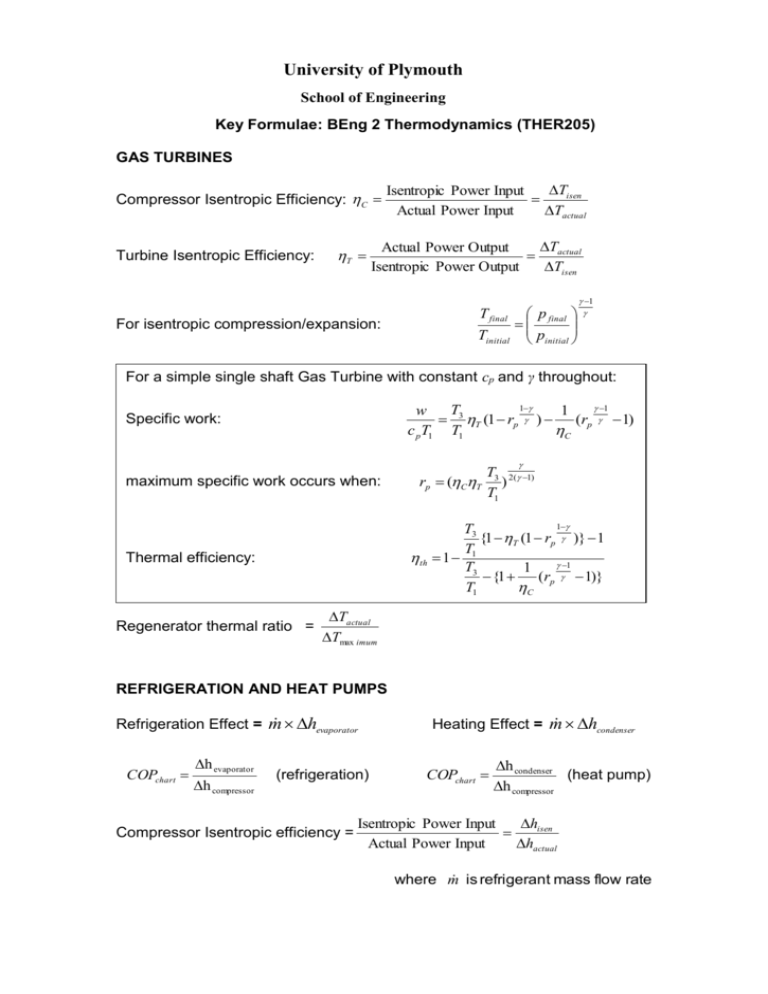
Compressor Isentropic Efficiency: C
Turbine Isentropic Efficiency:
T
Tisen
Isentropic Power Input
Actual Power Input
Tactual
T
Actual Power Output
actual
Isentropic Power Output
Tisen
For isentropic compression/expansion:
T final
Tinitial
p final
pinitial
1
For a simple single shaft Gas Turbine with constant cp and γ throughout:
1
1
T
w
1
3 T (1 rp ) (rp 1)
c pT1 T1
C
Specific work:
maximum specific work occurs when:
rp (CT
T3 2( 1)
)
T1
1
T3
{1 T (1 rp )} 1
T
th 1 1
1
T3
1
{1
(rp 1)}
T1
C
Thermal efficiency:
Regenerator thermal ratio =
Tactual
Tmax imum
REFRIGERATION AND HEAT PUMPS
hevaporator
Refrigeration Effect = m
COPchart
h evaporator
h compressor
(refrigeration)
Compressor Isentropic efficiency =
hcondenser
Heating Effect = m
COPchart
h condenser
(heat pump)
h compressor
hisen
Isentropic Power Input
Actual Power Input
hactual
where m is refrigerant mass flow rate
RECIPROCATING COMPRESSORS
Vclearance 1
r p n 1
Vswept
n 1
n
p inletVinduced (r p n 1)
n 1
Volumetric efficiency:
vol 1
Net Indicated Work per cycle:
Wnet
Stage pressure ratio for minimum work:
1
rp R p N
where Rp= overall pressure ratio, and N is the number of stages
ENERGY EFFICIENCY
Energy Conversion Efficiency =
Net (useful ) EnergyOutput
GrossEnergyInput
Annual heating cost for a heating plant:
24Q np
where
16.5 heat
Q design heat load (kW )
n number of degree days
p fuel cost(£/kWh )
heat average heating efficiency
STEADY STATE CONDUCTION
T
plane
Q
x
2T
Q
r
ln o
ri
2-D steady: at an internal node: T0=(T1+T2+T3+T4)/4
1-D steady:
on boundaries: isothermal
insulated (or symmetry)
cylindrical
Tw = const
Tw-1 = Tw+1
convective (plane surface)
T0 = (T1/2+T2+T3/2+BTf)/(2+B)
convective (external corner)
T0 = (T1/2+ T3/2+BTf)/(1+B)
convective (internal corner)
T0 = (T1/2+T2/2+T3+T4+BTf)/(3+B)
General conduction equation:
T
Q
2T
t
c p
B Grid Biot Number
thermal diffusivit y
ha
c p
CONVECTION
Q hA(Tw T f )
Basic equation:
Stanton Number: St
h
Vc p
Reynolds Analogy: St
f
2
Grashoff Number: Gr
Prandtl-Taylor modification: St
g 2l 3 T
2
f
1
2 1 rv (Pr 1)
where: rv = velocity ratio sub-layer:free stream = 1.99 Re -0.125 for smooth tubes
Nux 0.664 Re x 2 Pr
1
On a flat plate:
1
4
For fully developed turbulent flow in tubes: Nu 0.023 Re 0.8 Pr 0.4
HEAT EXCHANGERS
Basic design equations:
Q UATlog
1
thermal resistance s hot to cold
UA
Effectiveness of a counter flow heat-exchanger:
E
1 e NTU (1C )
1 Ce NTU (1C )
Effectiveness of a parallel flow heat-exchanger:
E
1 e NTU (1C )
1 C
FINS
For long ‘thin’ fins:
cosh m( L x)
0
cosh mL
For short ‘fat’ fins:
h
cosh m( L x)
sinh m( L x)
m
0
h
cosh mL
sinh mL
m
fin
and
h
tanh( mL)
m
fin
h
h
tanh( mL)
mL
1
m
m
Area weighted fin efficiency: 1 (1 fin )
On the finned side:
Q hA 0
where
tanh( mL)
mL
and
where m
A fin
A
hp
Ax
IC ENGINES
Air Standard thermal efficiencies:
For Dual Combustion Cycle :
1
1
th 1 1
rc 1 1
For Otto Cycle :
th 1
For Diesel Cycle : th
1
rc 1
1 1
1 1
rc 1
Volume at BDC : VBDC
rc
Vs
rc 1
Mean effective pressure (MEP) =
(where Vs is the stroke volume)
Wnet
Vs
Brake or Indicated Power = PLAN
P = BMEP or IMEP
L = stroke Length
A = piston face Area
N = No. of power strokes per sec.
BSFC =
Fuel Consumptio n
Brake Power
Volumetric efficiency (for 4-stroke naturally aspirated engines)
v
vol. of free air trapped per cycle
trapped mass
swept vol. of cylinder
theoretica l mass
i.e.
v
1
2
a
m
aVs N
