Heat Engines and the Carnot Cycle
advertisement
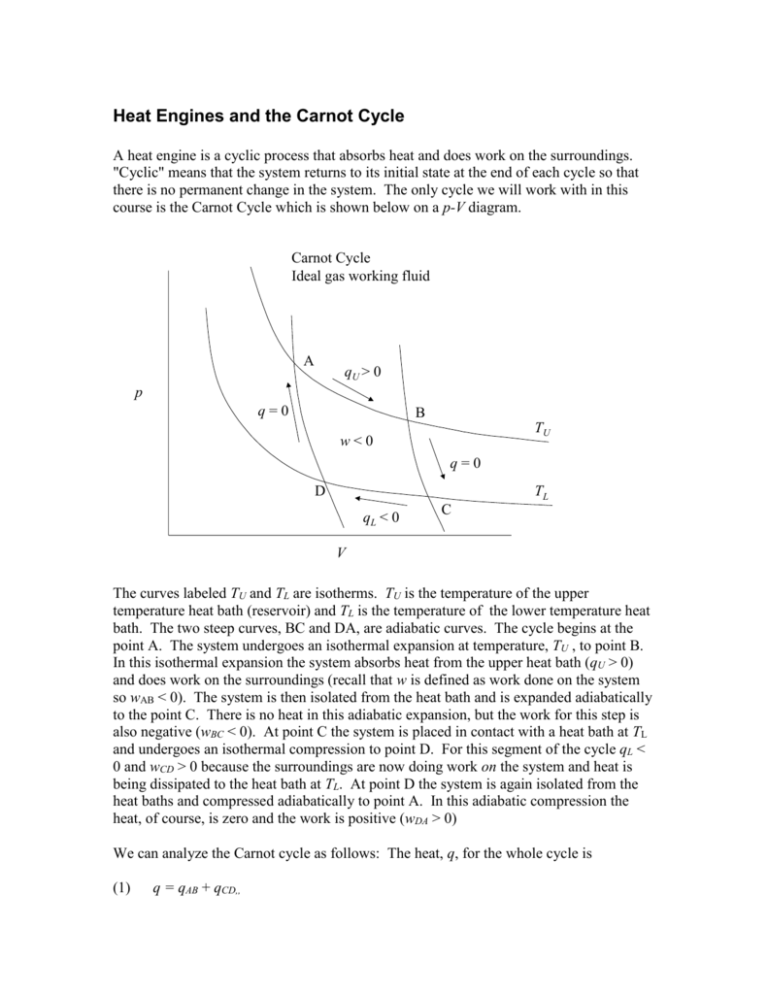
Heat Engines and the Carnot Cycle A heat engine is a cyclic process that absorbs heat and does work on the surroundings. "Cyclic" means that the system returns to its initial state at the end of each cycle so that there is no permanent change in the system. The only cycle we will work with in this course is the Carnot Cycle which is shown below on a p-V diagram. Carnot Cycle Ideal gas working fluid A qU > 0 p q=0 B TU w<0 q=0 TL D qL < 0 C V The curves labeled TU and TL are isotherms. TU is the temperature of the upper temperature heat bath (reservoir) and TL is the temperature of the lower temperature heat bath. The two steep curves, BC and DA, are adiabatic curves. The cycle begins at the point A. The system undergoes an isothermal expansion at temperature, TU , to point B. In this isothermal expansion the system absorbs heat from the upper heat bath (qU > 0) and does work on the surroundings (recall that w is defined as work done on the system so wAB < 0). The system is then isolated from the heat bath and is expanded adiabatically to the point C. There is no heat in this adiabatic expansion, but the work for this step is also negative (wBC < 0). At point C the system is placed in contact with a heat bath at TL and undergoes an isothermal compression to point D. For this segment of the cycle qL < 0 and wCD > 0 because the surroundings are now doing work on the system and heat is being dissipated to the heat bath at TL. At point D the system is again isolated from the heat baths and compressed adiabatically to point A. In this adiabatic compression the heat, of course, is zero and the work is positive (wDA > 0) We can analyze the Carnot cycle as follows: The heat, q, for the whole cycle is (1) q = qAB + qCD,, and the work for the entire cycle is, (2) w = wAB + wBC + wCD + wDA . Since the initial state of the cycle is the same as the final state we know that the change in U, the internal energy, is zero. (That's part of the first law, because the first law says that U is a state function, which means that the value of U for any state of the system does not depend on how the system got to that state, only on what the state actually is.) The first law of thermodynamics then tells us that (3) U q w 0 , from which we see that (4) q w . Notice that when the Carnot cycle is operating as a heat engine (going around clockwise), w < 0, so that -w > 0 and q > 0. As we have said, the Carnot cycle is a heat engine. That means that we want it to absorb heat and convert that heat energy into work. We certainly should care about how much work we get out for the heat we absorb. Thus we will define the efficiency, e, of a cycle as (5) e w , q AB which, when combined with Equations 1 and 4 gives (6) q q CD e AB q AB In order to conform to the usual notation we note that the AB segment of the cycle is at the temperature of the upper heat bath, TU, and the segment CD is at the temperature of the lower heat bath, TL. Thus equation 6 becomes (7) q qL q e U 1 L qU qU The AB and CD segments are an isothermal expansion of an ideal gas at TU and an isothermal compression at TL, respectively. For isothermal expansions and compressions of ideal gases, U q w 0 . Thus we can write (8) qU w AB nR T U ln VB VA q L wCD nR T L ln VD VC and (9) Let's plug these heats into Equation 7, (right hand side) to get, VD VC . e 1 VB nRTU ln VA nRTL ln (10) The nR cancels leaving, VD VC . e 1 VB TU ln VA TL ln (11) If we are looking for an expression for efficiency in terms of temperatures Equation 11 won't do the job because of all the volumes in the equation. However, there is another set of relations between the volumes from the fact that the paths BC and DA are adiabatic and we know the volume relationships for adiabatic processes in an ideal gas. Recall that for an adiabatic expansion of an ideal gas we had the expression (using the temperatures, pressures, and volumes appropriate to our Carnot cycle here) (12) pB V B pC V C for the BC segment of the cycle and a similar equation for the DA segment. (Recall that is the "heat capacity ratio," Cp/CV.) Let us eliminate the pressures from Equation 12 by inserting the value of pressure from the ideal gas equation of state, remembering that at points A and B the temperature is TU and at points C and D the temperature is TL. (13) nRTU nRTL VB VC. VB VC Cancel nR from both sides and combine the volumes to get, (14) TU V B1 TL V C1 From which we obtain (15) TU V C1 TL V B1 Note that there is an equivalent expression for the DA leg of the cycle, (16) TU V D1 . TL V A1 From these two last equations we conclude that 1 (17) 1 VC V D1 , 1 VB VA or (18) VC VB VD VA or, on rearranging, (19) VA VB VD. VC We now apply this result to Equation 11 to get, VA VB . e 1 VB TU ln VA TL ln (20) The two logarithms are the negatives of each other so we conclude that, (20) e 1 TL TU TL . TU TU Notice that the highest efficiencies are obtained with a low temperature for the heat bath at TL and that you could only obtain unit efficiency if the lower heat bath were at absolute zero. Since, in most cases, TL is constrained by the surroundings engineers try to use the highest feasible operating temperature, TU . Real heat engines, of course, are not Carnot cycles, but the second law of thermodynamics requires that no heat engine operating between TU and TL can have an efficiency greater than a Carnot cycle efficiency. So the Carnot cycle provides an idealized upper limit to the efficiency of heat engines. Even though the Carnot cycle is idealized the general principles of heat engines remain the same. If your lower temperature, TL, is constrained (by design or operating considerations) you can increase the efficiency of your heat engine by increasing TU. If your upper temperature, TU, is constrained you can increase the efficiency by lowering TL.
