CRS-48-07e APTS_manual_summary_draf…
advertisement
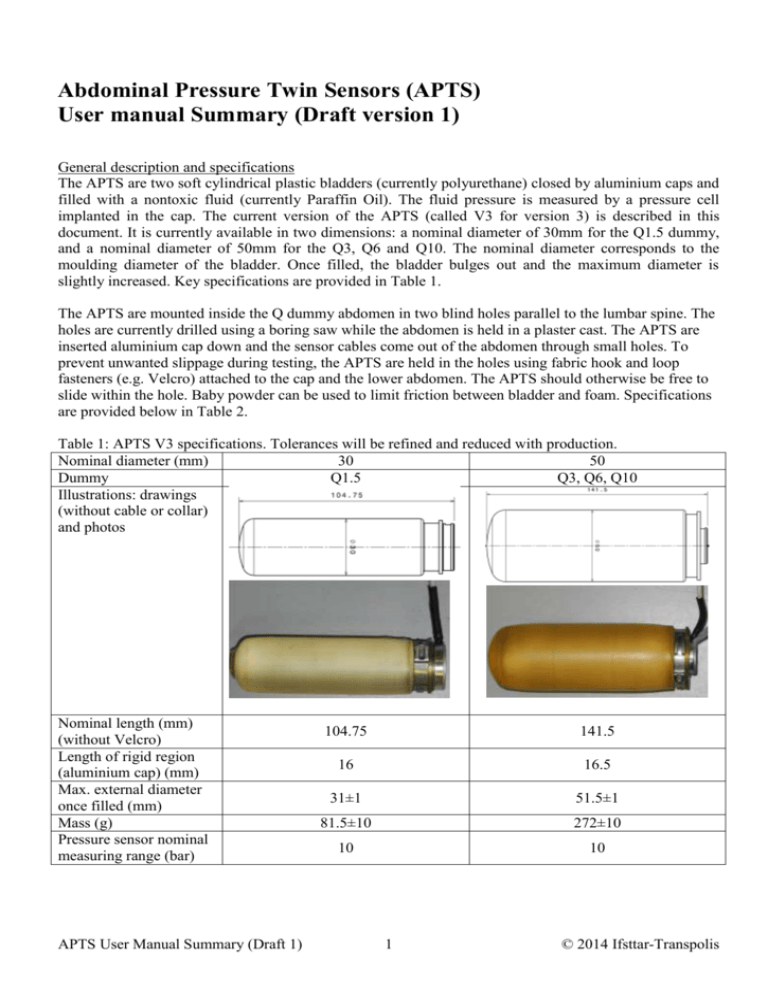
Abdominal Pressure Twin Sensors (APTS) User manual Summary (Draft version 1) General description and specifications The APTS are two soft cylindrical plastic bladders (currently polyurethane) closed by aluminium caps and filled with a nontoxic fluid (currently Paraffin Oil). The fluid pressure is measured by a pressure cell implanted in the cap. The current version of the APTS (called V3 for version 3) is described in this document. It is currently available in two dimensions: a nominal diameter of 30mm for the Q1.5 dummy, and a nominal diameter of 50mm for the Q3, Q6 and Q10. The nominal diameter corresponds to the moulding diameter of the bladder. Once filled, the bladder bulges out and the maximum diameter is slightly increased. Key specifications are provided in Table 1. The APTS are mounted inside the Q dummy abdomen in two blind holes parallel to the lumbar spine. The holes are currently drilled using a boring saw while the abdomen is held in a plaster cast. The APTS are inserted aluminium cap down and the sensor cables come out of the abdomen through small holes. To prevent unwanted slippage during testing, the APTS are held in the holes using fabric hook and loop fasteners (e.g. Velcro) attached to the cap and the lower abdomen. The APTS should otherwise be free to slide within the hole. Baby powder can be used to limit friction between bladder and foam. Specifications are provided below in Table 2. Table 1: APTS V3 specifications. Tolerances will be refined and reduced with production. Nominal diameter (mm) 30 50 Dummy Q1.5 Q3, Q6, Q10 Illustrations: drawings (without cable or collar) and photos Nominal length (mm) (without Velcro) Length of rigid region (aluminium cap) (mm) Max. external diameter once filled (mm) Mass (g) Pressure sensor nominal measuring range (bar) APTS User Manual Summary (Draft 1) 104.75 141.5 16 16.5 31±1 51.5±1 81.5±10 272±10 10 10 1 © 2014 Ifsttar-Transpolis Table 2: Holes specifications. The lower abdomen skin should be preserved (except for holes needed to pass the cables and Velcros). All tolerances are estimated based on surface scans of the first abdomens. Tolerances will be refined and reduced with production abdomens. Dummy Q1.5 Q3 Q6 Q10 Illustration Orientation Diameter (mm) Spacing (mm) Location (mm) Parallel to spine (within 5 degrees), symmetric location (left/right, within 2mm) 32.5±2 53±2 51±2 65±2 61±2 100±2 22±4 from plane 66±4 from axis of 70±4 from plane 84±3 from plane in cylinder in back of in back of back of abdomen abdomen abdomen Drilling depth stop just before reaching the skin End of hole Lower skin is visible* Flat* * The hole should be finished manually (e.g. with a blade) to prevent skin damage Response verification The APTS have been designed to have limited effects on the compressive response of the abdomen. To verify their response, a simplified static procedure is used. Key dimensions of the fixture needed for the verification and illustrations of the procedure are provided in the Figure 1 below. In summary: - Position the bladder on a horizontal beam (50mm wide) with free space below. - Place a 46 mm wide belt mounted on a U-shaped frame (total weight 2±0.02 kg) over the bladder, with the frame hanging below the beam. The belt midline should be perpendicular to the axis of the bladder and centred on the middle of the deformable component. - Between 30 and 45s after the weight is applied, measure the belt height over the bladder (using a calliper mounted on a magnetic arm) and the pressure value. The frame should not be moving while the measurements are performed. - Hang an additional 25.516±0.02 kg to the frame - Between 30 and 45s after the weight is applied, measure the belt height (using the calliper) and the pressure value. The frame should not be moving while the measurements are performed. - Remove the frame from the bladder. - Calculate the difference of belt height (displacement) and the difference of pressure between the two positions. The displacement should be 10.6mm (±13%) for the APTS 30mm, and 16.2mm (±13%) for the APTS 50mm. The pressure variation should be 1.01bar (±13%) for the APTS 30mm and 0.59 bar (±13%) for the APTS 50mm. Tolerances will be refined and reduced with production. APTS User Manual Summary (Draft 1) 2 © 2014 Ifsttar-Transpolis 1 3 2 Figure 1: Static verification procedure. Left: setup overview with key dimensions. A standard belt (46mm wide, 480mm long) is mounted on a U-shaped frame using 10mm diameter axes spaced 450mm apart (total mass m=2kg). The frame has a hole to hang an additional mass (M=25.516kg). Right: verification steps (the bladder deformation is not shown on the diagrams): (1) the bladder is positioned on a horizontal beam (2) the belt is positioned over the centre of the bladder with the frame hanging below the beam. Initial height (calliper, with example of photo) and pressure are measured (3) The mass M is added and the measurements are repeated. Installation procedure: The APTS are first installed in the abdomen outside the dummy using the following procedure: - Pass the connectors and cables through the holes at the bottom of the abdomen. - Powder the bladders and holes with baby powder before inserting the APTS. - Push the bladders to the bottom of the hole while pulling simultaneously on the cables. The sensors should be free to slide. - Q3, Q6, Q10: Pass the Velcro through the small holes at the bottom and secure them. - Check that the APTS are holding in place by pulling gently on them. - Mount the abdomen with APTS in the dummy using the procedure specified by the dummy manufacturer. The cables should exit the dummy in the back near the lumbar spine. Ensure that there is sufficient cable slack to prevent damage. For removal, follow the installation procedure in the reverse order. APTS User Manual Summary (Draft 1) 3 © 2014 Ifsttar-Transpolis Checks and data processing: After each test: verify that the APTS are still in place: check the upper bladder position with respect to the abdomen. If the APTS have moved upwards (typically 2cm or more) then the test results may not be valid and the APTS must be checked for damage (cable, Velcro, etc). Every 10 tests (when checking the abdomen): check the Velcro, cable, and add baby powder if needed. Data processing: pressure signals should be filtered using a CFC 180 filter. The pressure signals should be zeroed using the pressure value just prior to the test (with the dummy in position). The maximum pressure criterion is the maximum of the left and right pressure (filtered and zeroed). APTS User Manual Summary (Draft 1) 4 © 2014 Ifsttar-Transpolis
