PSoC 4 Lab 2 - PWM LED - Lab Manual
advertisement

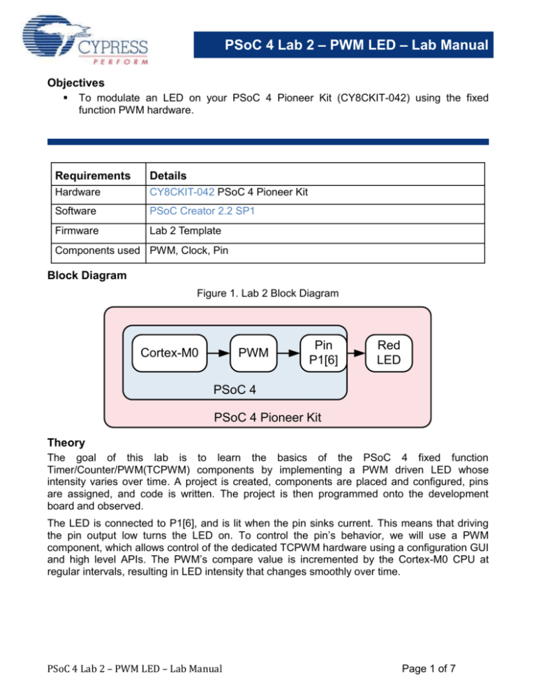
PSoC 4 Lab 2 – PWM LED – Lab Manual Objectives To modulate an LED on your PSoC 4 Pioneer Kit (CY8CKIT-042) using the fixed function PWM hardware. Requirements Details Hardware CY8CKIT-042 PSoC 4 Pioneer Kit Software PSoC Creator 2.2 SP1 Firmware Lab 2 Template Components used PWM, Clock, Pin Block Diagram Figure 1. Lab 2 Block Diagram Cortex-M0 PWM Pin P1[6] Red LED PSoC 4 PSoC 4 Pioneer Kit Theory The goal of this lab is to learn the basics of the PSoC 4 fixed function Timer/Counter/PWM(TCPWM) components by implementing a PWM driven LED whose intensity varies over time. A project is created, components are placed and configured, pins are assigned, and code is written. The project is then programmed onto the development board and observed. The LED is connected to P1[6], and is lit when the pin sinks current. This means that driving the pin output low turns the LED on. To control the pin’s behavior, we will use a PWM component, which allows control of the dedicated TCPWM hardware using a configuration GUI and high level APIs. The PWM’s compare value is incremented by the Cortex-M0 CPU at regular intervals, resulting in LED intensity that changes smoothly over time. PSoC 4 Lab 2 – PWM LED – Lab Manual Page 1 of 7 PSoC 4 Lab 2 – PWM LED – Lab Manual Procedure – Firmware 1) Open the PSoC 4 Intro Lab Templates workspace by double-clicking on the “PSoC 4 Intro Lab Templates.cywrk” file in the Lab Templates directory. You will be presented with a workspace in PSoC Creator containing one template project for each of the labs after lab 1. 2) Set the Lab 2 template project as the active project by right-clicking on it in the Workspace Explorer, and clicking on the “Set As Active Project” option. This step is shown in Figure 2. This causes PSoC Creator to perform actions on this project instead of the other projects in the workspace. In its initial state, this project will blink the red LED at 1 Hz, as we implemented in the first lab. Figure 2. PSoC Creator “Set As Active Project” Action PSoC 4 Lab 2 – PWM LED – Lab Manual Page 2 of 7 PSoC 4 Lab 2 – PWM LED – Lab Manual 3) Open the project’s schematic by double-clicking on the “TopDesign.cysch” file in the Workspace Explorer. Note that in this schematic, we’ve included off-chip annotation components to show how the red LED is connected to the pin. 4) Open the Pin_Red component customizer by double-clicking on the component in the schematic. Check the “HW Connection” checkbox to enable hardware control of the pin. Click the “OK” button to apply changes and close the customizer. 5) In the component catalog, under the “Digital -> Functions” category, select the “PWM (TCPWM mode)” component, and drag it into the schematic. Place it in the box labeled “Place PWM here.” At this point, please ensure to correctly line up the “line” terminal with the “Pin_Red” Pin Component. 6) In the component catalog, under the “System” category, select the Clock component, and drag it into the schematic. Place it such that its output is connected to the clock input of the PWM. The result is shown in Figure 3. Figure 3. Schematic With PWM and Clock Placed PSoC 4 Lab 2 – PWM LED – Lab Manual Page 3 of 7 PSoC 4 Lab 2 – PWM LED – Lab Manual 7) Open the PWM’s component customizer by double-clicking on it. Select the PWM tab to edit PWM-specific behavior. Change the “Period” value to 1000, and the “Compare” value to 0. Press the “OK” button. The customizer window is shown in Figure 4. Figure 4. PWM Configuration Window with Period and Compare Set PSoC 4 Lab 2 – PWM LED – Lab Manual Page 4 of 7 PSoC 4 Lab 2 – PWM LED – Lab Manual 8) In the “Workspace Explorer”, double-click the “main.c” file to open it in the code editor. 9) Replace the “Change1” line with the PWM start API, shown in Code 1. Code 1. Lab 2 PWM Start API Code PWM_1_Start(); 10) Replace the “Change2” line with the PWM start API, shown in Code 2. The entire main.c should look like that shown in Figure 5. Code 2. Lab 2 PWM Write Compare API Code PWM_1_WriteCompare(PWMCompare); Figure 5. Lab 2 Solution main.c PSoC 4 Lab 2 – PWM LED – Lab Manual Page 5 of 7 PSoC 4 Lab 2 – PWM LED – Lab Manual 11) Press the “Program” button on the PSoC Creator toolbar to build the project and program your kit. At this point, your red LED should start displaying a sawtooth-shaped brightness waveform at 1 Hz. Procedure – CY8CKIT-042 Hardware Setup 12) No hardware setup is required for this project. The red LED cathode is connected to P1[6] with a copper trace. Conclusion You have successfully implemented variable duty-cycle PWM drive of the red LED on your kit. This technique can be applied to a number of different transducers. The TCPWMs may also be used for many other purposes, such as motor control or precise timing and counting of digital signals. Stretch Goals Implement a different brightness waveform. o We have implemented a sawtooth waveform by incrementing the compare value until it rolls over. o Try creating a triangle wave by incrementing to a limit, then decrementing back down to zero. o Try implementing a lookup table to create an arbitrary waveform like a sine wave. Drive multiple LEDs to create a combination of colors. o We are driving the red LED out of the tri-color array using P1[6]. The green LED is attached to P0[2]. The blue LED is attached to P0[3]. o Add two more PWMs to control the other colors, and vary their compare values along with that of the red LED to mix the colors together. PSoC 4 Lab 2 – PWM LED – Lab Manual Page 6 of 7 PSoC 4 Lab 2 – PWM LED – Lab Manual Document Revision History Revision By Description 01 MAXK First Release PSoC 4 Lab 2 – PWM LED – Lab Manual Page 7 of 7


