Section #23 52 00 - Heating Boilers
advertisement
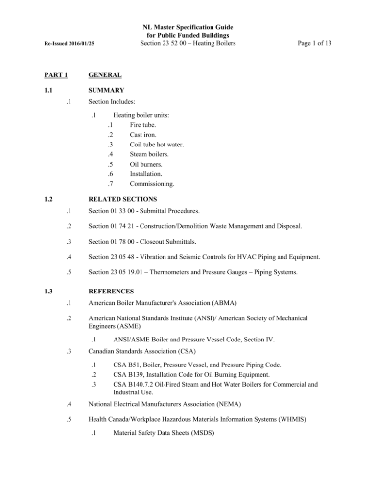
NL Master Specification Guide for Public Funded Buildings Section 23 52 00 – Heating Boilers Re-Issued 2016/01/25 PART 1 GENERAL 1.1 SUMMARY .1 Section Includes: .1 1.2 Page 1 of 13 Heating boiler units: .1 Fire tube. .2 Cast iron. .3 Coil tube hot water. .4 Steam boilers. .5 Oil burners. .6 Installation. .7 Commissioning. RELATED SECTIONS .1 Section 01 33 00 - Submittal Procedures. .2 Section 01 74 21 - Construction/Demolition Waste Management and Disposal. .3 Section 01 78 00 - Closeout Submittals. .4 Section 23 05 48 - Vibration and Seismic Controls for HVAC Piping and Equipment. .5 Section 23 05 19.01 – Thermometers and Pressure Gauges – Piping Systems. 1.3 REFERENCES .1 American Boiler Manufacturer's Association (ABMA) .2 American National Standards Institute (ANSI)/ American Society of Mechanical Engineers (ASME) .1 .3 ANSI/ASME Boiler and Pressure Vessel Code, Section IV. Canadian Standards Association (CSA) .1 .2 .3 CSA B51, Boiler, Pressure Vessel, and Pressure Piping Code. CSA B139, Installation Code for Oil Burning Equipment. CSA B140.7.2 Oil-Fired Steam and Hot Water Boilers for Commercial and Industrial Use. .4 National Electrical Manufacturers Association (NEMA) .5 Health Canada/Workplace Hazardous Materials Information Systems (WHMIS) .1 Material Safety Data Sheets (MSDS) NL Master Specification Guide for Public Funded Buildings Section 23 52 00 – Heating Boilers Re-Issued 2016/01/25 .6 1.4 Page 2 of 13 Province of Newfoundland and Labrador Boiler, Pressure Vessel and Compressed Gas Regulations. SUBMITTALS .1 Product Data: .1 .2 Submit manufacturer’s printed product literature, specifications and datasheet in accordance with Section 01 33 00 – Submittals Procedures. Include product characteristics, performance criteria, and limitations. .1 Submit two copies of Workplace Hazardous Materials Information System (WHMIS) Material Safety Data Sheets (MSDS) in accordance with Section 01 33 00 – Submittal Procedures. Shop Drawings: .1 .2 .3 .4 Submit shop drawings in accordance with Section 01 33 00 – Submittal Procedures. Indicate the following: .1 General arrangement showing terminal points, instrumentation test connections. .2 Clearances for operation, maintenance, servicing, tube cleaning, tube replacement. .3 Foundations with loadings, anchor bolt arrangements. .4 Piping hook ups. .5 Equipment electrical drawings. .6 Burners and controls. .7 All miscellaneous equipment. .8 Flame safety control systems. .9 Breeching and stack configuration. .10 Stack emission continuous monitoring system to measure CO, O, NOx, SO, stack temperature and smoke density of flue gases. Engineering data to include: .1 Boiler efficiency at 25%, 50%, 75%, 100%, and 110% of design capacity. .2 Radiant heat loss at 100% design capacity. .3 Quality assurance submittals: submit following in accordance with Section 01 33 00 – Submittal Procedures. .1 Certificates: submit certificates signed by manufacturer certifying that materials comply with specified performance characteristics and physical properties. .2 Instructions: submit manufacturer’s installation instructions. Closeout Submittals: .1 Submit operation and maintenance data for incorporation into manual specified in Section 01 78 00 – Closeout Submittals. NL Master Specification Guide for Public Funded Buildings Section 23 52 00 – Heating Boilers Re-Issued 2016/01/25 1.5 Page 3 of 13 QUALITY ASSURANCE .1 Regulatory Requirements: work to be performed in compliance with Canadian Environmental Protection Act (CEPA), Canadian Environmental Assessment Act (CEAA), Transportation of Dangerous Goods Act (TDGA), and applicable Provincial regulations. .2 Health and Safety: .1 1.6 Do construction occupational health and safety in accordance with Section 01 35 29.06 – Health and Safety Requirements. DELIVERY, STORAGE, AND HANDLING .1 Packing, shipping, handling and unloading: .1 .2 Waste Management and Disposal: .1 .2 1.7 Deliver, store and handle in accordance with manufacturer’s written instructions and Section 01 61 00 – Common Product Requirements. Construction/demolition waste management and disposal: separate waste materials for reuse and recycling in accordance with Section 01 74 21 – Construction/Demolition Waste Management and Disposal. Remove from site and dispose of packaging materials at appropriate recycling facilities. MAINTENANCE .1 Extra materials: .1 .2 .3 .4 .5 .6 .7 .8 Special tools for burners, manholes, handholes and operation and maintenance. Spare parts for 1 year of operation. Spare gaskets – 1 set. Spare gauge glass inserts – 1 of each size and type. Probes and sealants for electronic indications – 1 set. Spare burner tips – 1 set. Spare burner gun – 1. Safety valve test gauge – 1. PART 2 PRODUCTS 2.1 GENERAL .1 Packaged boiler: .1 .2 Complete with burner and necessary accessories and controls. Laboratory tested at rated capacity to, and bearing seal or nameplate certifying compliance with, CSA B140.7.2 . NL Master Specification Guide for Public Funded Buildings Section 23 52 00 – Heating Boilers Re-Issued 2016/01/25 .3 .4 .5 .6 .2 Ready for attachment to piping, electrical power, controls, flue gases exhaust. Designed and constructed to ANSI/ASME Boiler and Pressure Vessel Code. CRN (Canadian Registration Number), to CSA B51 and authority having jurisdiction. Boiler/burner package to bear ULC label. Performance: .1 .2 .3 .4 .5 .3 In accordance with American Boiler Manufacturers Association (ABMA) testing procedures. Steam: design steam pressure: 860 kPa capacity as indicated. Operating hot water: capacity as indicated. Firing rate: #2 oil. As indicated. Boiler efficiency: 80 % minimum at 30% to 100% firing rates. Flue gas temperature leaving boiler: .1 Not to exceed 260oC. .2 Above dewpoint conditions at minimum firing rate. Electrical: .1 .2 .3 Power: 600 V, 3 phase, 60Hz. Controls: 120 V, 1 phase, 60Hz. Electrical components: CSA approved. .4 Controls: factory wired. NEMA 1steel cabinet .5 Thermal insulation: .1 50 mm thick mineral fibre. Seal insulation at handholes, manholes, mudholes, piping connections with insulating cement or asphaltic paint. Finish with heat resisting paint. .6 Jackets: heavy gauge metal, finished with heat resisting paint. .7 Mounting: .1 .8 Page 4 of 13 Structural steel base, lifting lugs. Anchor bolts and templates: .1 Supply for installation by other Divisions. Anchor bolts to be sized to Section 23 05 48 - Vibration and Seismic Controls for HVAC Piping and Equipment. .9 Start-up, instruction, on-site performance tests: three (3) working days per boiler. .10 Trial usage: .1 .2 Owner’s Representative may use boilers for test purposes prior to acceptance and commencement of warranty period. Supply labour, materials and instruments required for tests. Re-Issued 2016/01/25 .11 Page 5 of 13 Temporary use by contractor: .1 .2 .3 2.2 NL Master Specification Guide for Public Funded Buildings Section 23 52 00 – Heating Boilers Contractor may use boilers providing warranty is not affected and only after written approval from Owner’s Representative. Monitor and record performance continuously. Keep log of maintenance activities carried out. Refurbish to as-new condition before final inspection and acceptance. FIRETUBE BOILER .1 General: .1 .2 Design: .1 .2 .3 .4 .5 .6 .7 2.3 Packaged, Scotch dryback or wetback, 3 multi pass, with 26 kW/m2, total effective fireside heating surface as indicated. Forced draft. Furnace tube centrally located in boiler shell. Tube bundle arranged to facilitate water circulation and prevent sludge accumulation. Tubes rolled and beaded into tube sheets, accessible for cleaning and replacement. Combustion chamber: refractory lined. Access for cleaning water side: at least one manhole and adequate number of handholes. Hinged or davitted gasketted front and rear heads with access to tube sheets without removal of any front end equipment. CAST IRON BOILER .1 Sectional, forced draft firing, waterwall design, complete with factory assembled or site assembled water cooled sections, front plate and removable panels. .2 Design of sections to provide balanced water circulation and flue gas travel. Make sections gas-tight and water-tight through use of high temperature rope, nipples, pull-up bolts. .3 Flue passages: readily accessible without use of special tools. .4 Provide supply and return headers, elbows to manufacturers recommendations and to suit installation. .5 Include mudholes, inspection and cleanout handholes. 2.4 COIL TUBE HOT WATER BOILER .1 Packaged, forced circulation, water tube type, employing multiple parallel coiled tubes, forced draft firing, refractory lined combustion chamber, fully modulating burner. NL Master Specification Guide for Public Funded Buildings Section 23 52 00 – Heating Boilers Re-Issued 2016/01/25 Page 6 of 13 .2 Water Content: as indicated. .3 The steam generator to be installed within an air casing pressurized by the combustion air blower. Feedwater, fuel, and air to be metered to the steam generator as a function of steam pressure. .4 The steam generator to be equipped with an electronic excess steam pressure control, burner, and automatic ignition. The steam generating section to be removable from the back of the unit. The saturated steam generator, auxiliaries, and controls to be mounted on a common base, all components on the base to be piped and wired. Components furnished include the circulating pump, forced draft blower, steam drum, pressure control instruments, temperature control instruments, pressure gauges, motor starters and push-buttons, control transformer, feedwater controls, steam safety valve, thermocouple, and other components required for a complete steam generator. .5 No difference in steam quality across the entire operating range of the steam generator. .6 Performance Characteristics: .1 .2 .3 .4 .5 .6 .7 .8 .9 .10 .11 .12 .13 Quantity as indicated. Boiler horsepower Maximum thermal output Minimum thermal output Turndown ratio Design pressure Stream quality Fuel Atomizing Air requirement Fuel consumption Combustion/ventilation air Line voltage Control voltage .7 Dimensions: as Indicated. .8 Components: .1 .2 as indicated. as Indicated. as Indicated. as Indicated. 5:1 (minimum) 1034 kPag 99.5%+ No. 2 as Indicated. as Indicated. as Indicated. 575 VAC, 3PH, 60 Hz. 120 VAC, 1PH, 60 Hz. Steam generator: .1 The steam generator to consist of a separate combustion chamber to isolate the flame from the coil section to prevent flame impingement on the coils, convection type steam generating section, and steam drum. Tube materials in the steam generator to be in accordance with ASME specifications. The steam generating section to consist of multiple parallel-connected individual coils, 689 kPa design pressure. Boiler shell insulated and covered with steel jacket. Pressure control: NL Master Specification Guide for Public Funded Buildings Section 23 52 00 – Heating Boilers Re-Issued 2016/01/25 .1 .3 .4 .5 .6 .7 .8 Page 7 of 13 The pressure control to automatically adjust fuel and air to suit steam demand. The accuracy of this control to be plus or minus three percent (3%) of the pressure adjustment range. Safety: .1 All features of the design to ensure safe and reliable operation. Installed controls to shut off the fire if temperature, pressure, or both exceed set limits. The steam generator to be fail-safe in the event of power failure. Fuel and combustion air systems to be electrically interlocked to shut fuel to the burner in case of combustion air failure. .2 The steam generator to have an electronic steam temperature control, which requires a manual reset located on the boiler control panel. This steam temperature control, a thermocouple, which, due to its placement, directly monitors the maximum possible outlet temperature of each coil, and extinguishes the fire in the steam generator in the event that steam temperature reaches a preset point. Piping: .1 All pressure piping to be designed and constructed in accordance with applicable provisions of the ASME Boiler and Pressure Vessel Code for Power Boilers. Recirculating pump: .1 A centrifugal type pump to be driven by an electric motor. The pump to be ASME approved. The pump to have a top horizontal discharge for efficient elimination of possible vapors in the fluid, enclosed impeller for high efficiency, oil lubricated standard ball bearing for long life and low maintenance graphite ribbon packing or tungsten carbide mechanical seals depending on operating pressures, cooling water jacket on medium and high pressure units, alloy steel shaft, and stainless steel sleeve and impeller bolt. Combustion air blower: .1 The steam generator equipped with a motor driven centrifugal combustion air blower. The blower to be of the non-overloading, backward curve type. Burners: .1 The steam generator equipped with a forced draft burner, for number 2 fuel oil. The burner to be located at the end of a horizontal or vertical refractory lined combustion chamber. The number 2 fuel oil burner to be a wide range burner of the air atomizing type, gas pilot ignited, fully modulating. .2 Burner control system to include automatic burner sequencing, flame supervision, status indication, first-out annunciation, and self-diagnosis. .3 An ultraviolet sensitive flame detector to monitor the flame in the combustion chamber of the steam generator. Steam drum: .1 The steam drum to be constructed in accordance with the latest ASME requirements. The drum designed to separate water from steam so that Re-Issued 2016/01/25 .9 .10 NL Master Specification Guide for Public Funded Buildings Section 23 52 00 – Heating Boilers Page 8 of 13 the steam quality will be ninety-nine percent (99%) or greater. The drum to be insulated and covered with metal sheathing. Control panel: .1 The control panel to include pressure gauges, temperature indicators, control power transformer, and other controls as required. .2 The control panel to have the following annunciators at a minimum: .1 Control power on indicator. .2 Burner on light. .3 Flame out light and audible alarm. .4 High coil temperature light and audible alarm. .5 Low combustion air and audible alarm. .6 Low atomizing air and audible alarm. .7 High water light and audible alarm. .8 Low water level cut-off and alarm. .9 Other alarms as required by Province of Newfoundland & Labrador, Service NL for guarded plant status. .3 Provide necessary relays and communication ports as required to permit each boiler to communicate with the proposed EMCS system. Each boiler to have four points communicating with the EMCS system: .1 Steam drum pressure (provide pressure sensor tapping). .2 Boiler enable (Provide auxiliary contacts) .3 Firing Rate (4-20 mA input signal from EMCS to boiler controller). .4 Common Alarm (Provide auxiliary contacts/relays as required to communicate any/all boiler alarms to EMCS system as a single common alarm). Separate alarms for low water, flame failure, boilers offline. The EMCS system to interface with the boilers to provide for automatic lead/lag control sequencing, set operating setpoints and control firing rates. Co-ordinate all requirements with the Owner’s Representative and the Owner prior to submission of shop drawings. .4 The following components to be included as part of each boiler control package: .1 One (1) microprocessor based integrated burner control for automatic oil firing. The relay module to be located in the system micro computer to generate fault messages and descriptions and processes burner I/O. .2 One (1) expanded annunciator. .5 Boilers to be capable of transmitting boiler failure alarms or all other parameters to the EMCS system. Co-ordinate required control interfacing with the Owner’s Representative prior to shop drawing submission. Auxiliaries: NL Master Specification Guide for Public Funded Buildings Section 23 52 00 – Heating Boilers Re-Issued 2016/01/25 .1 .2 .3 .4 .5 .6 .7 .8 .9 .10 .11 .12 .13 .14 .15 2.5 Page 9 of 13 ANSI/ASME rated safety relief valve, set at 455 kPa, sized to release entire boiler capacity. High water level device. Low water level device. Water level controller and feedwater control valve. Surface blowdown isolation valves. Atomizing air solenoid and isolation valves. Pilot gas (propane) isolation and regulator valves. Fuel oil pump complete with integral relief valve, filter, isolation valve, fusible valve, solenoid valve. Gauges for fuel oil, atomizing air. Steam stop/check valve. Quick opening bottom blowdown valve and slow opening bottom blowdown valve. Stack thermometer, range 65 to 400OC. Drain valve, 50 mm. Pressure sensitive controls to regulate the flow of fuel and air to burner for maximum burner efficiency throughout the operating range. Flame observation port. AUXILIARIES .1 Provide for each boiler and to meet ANSI/ASME requirements. .2 Hot water boilers: .1 .2 .3 .4 .5 .6 .7 .8 .9 .10 .3 Relief valves: ANSI/ASME rated, set at 200 kPa, to release entire boiler capacity. Pressure gauge: to Section 23 05 19.01 – Thermometers and Pressure Gauges – Piping Systems, two times normal operating range. Thermometer: to Section 23 05 19.01 – Thermometers and Pressure Gauges – Piping Systems range two times normal operating range. Low water cut-off: with visual and audible alarms. Auxiliary low water cut-off: with separate cold water connection to boiler. Isolating gate valves: on supply and return connections. Drain valve: NPS 2. Stack thermometer: Range 65 to 400 oC. Outdoor controller: to reset operating temperature controller. One 1 set of cleaning tools. Steam boilers: .1 Safety valves : ANSI/ASME rated, set at 100 or 860 kPa , to release entire boiler capacity, complete with drip pan elbow and vent pipe. NL Master Specification Guide for Public Funded Buildings Section 23 52 00 – Heating Boilers Re-Issued 2016/01/25 Pressure gauge: to Section 23 05 19.01 – Thermometers and Pressure Gauges – Piping Systems range 0 to 200 kPa, or 0 to 1800 kPa complete with siphon and ball valve. Water column assembly: with tri-cocks, gauge glass, protective rods, blowdown valves operated from firing floor. High water level: audible alarm. Low water level: fuel cut-off with visual and audible alarms and feedwater pump control switch. Feedwater regulator on 3-valve bypass with drain valve, stop valve and check valve. Continuous blow-down stop valve. Soot blower element, supply valve and drain valve. Auxiliary low water cut-off with separate cold water connection to boiler. Steam stop-check valve. Quick-opening blowdown valve and shut-off valve. Stack thermometer: range 65 to 400 oC. Drain valve: NPS 2. One 1 set cleaning tools. .2 .3 .4 .5 .6 .7 .8 .9 .10 .11 .12 .13 .14 .4 2.6 Page 10 of 13 Pot type chemical feeder. OIL BURNERS .1 General: .1 .2 Pressure-mechanical atomizing forced draft with: .1 Built-in blower to supply combustion air, complete with motor, silencer and damper. .2 Two stage oil pump driven by blower motor and complete with integral relief valve. .3 Oil filter. .4 Pressure gauge. .5 High voltage ignition transformer. .6 Flame observation port. .7 Easy access to nozzles and electrodes. .8 Oil and air metering controls for maximum burner efficiency throughout operating range. Electric oil heater: to heat fuel oil from pre-heat temperature to combustion temperature, even with voltage reduced by 20%, complete with 63 mm diameter thermometer on inlet and outlet. .2 Turndown ratio: at least 3:1. .3 Controls: Re-Issued 2016/01/25 .1 .2 .3 .4 .5 .6 .7 .8 2.7 NL Master Specification Guide for Public Funded Buildings Section 23 52 00 – Heating Boilers Page 11 of 13 Electronic combustion control relay with scanner for combustion control and flame supervision. Control to shut off fuel within 5 seconds upon flame failure or upon signal of safety interlock and to ensure, when restarted, in sequence, ignition and resumption of supervision of burner operation. Burner operation to include: .1 Pre-purge. .2 Pilot ignition and supervision. .3 Burner operation. .4 Post-purge upon burner shut-down. Immersion controllers: .1 Operating: to start and stop burner, and operating between adjustable setpoints. .2 High-low: to shift burner operation to high or low fire. .3 Modulating: to modulate burner output. .4 High limit: manual reset, As indicated . .5 Controller range: As indicated . Visual and audible alarms: to indicate burner shutdown due to flame failure, low water level, high pressure, low air pressure, low fuel pressure, low fuel temperature. Selector switch: to permit manual and automatic firing at any rate between low and high fire. Pilot lights: to indicate: .1 Normal burner operation .2 All stages of burner operation. Burner to start up in low fire position. EMISSION CONTROL .1 Rate of discharge of air contaminants from boiler not to exceed: .1 .2 .3 For nitrogen oxides expressed as nitrogen dioxide: .1 43 ng/J of heat input when fired with oil specified as type 1 or 2, according to CGSB classification. .2 22 ng/J of heat input when fired with gaseous fuel. For sulphur dioxide: .1 25 ng/J of heat input when fired with oil specified as type 1 or 2, according to CGSB classification. For carbon monoxide, 125 ng/J of heat input. NL Master Specification Guide for Public Funded Buildings Section 23 52 00 – Heating Boilers Re-Issued 2016/01/25 PART 3 EXECUTION 3.1 INSTALLATION Page 12 of 13 .1 Install in accordance with ANSI/ASME Boiler and Pressure Vessels Code Section IV, regulations of Province having jurisdiction, except where specified otherwise, and manufacturers recommendations. .2 Make required piping connections to inlets and outlets recommended by boiler manufacturer. .3 Maintain clearances as indicated or if not indicated, as recommended by manufacturer for operation, servicing and maintenance without disruption of operation of any other equipment/system. .4 Mount unit level. .5 Pipe hot water relief valves full size to nearest drain. .6 Pipe steam relief valve through roof with drip pan elbow piped to nearest drain. .7 Pipe blowdown/drain to blowdown tank/floor drain. .8 Oil fired installations - in accordance with CSA-B139. .9 All boilers to be approved by the local authorities having jurisdiction. Obtain all required inspections and approvals prior to start-up and commissioning. Provide copies of affidavits, approval letters, etc., to the Owner’s Representative for record purposes. 3.2 MOUNTINGS AND ACCESSORIES .1 Safety valves and relief valves: .1 .2 .3 .2 Blowdown valves: .1 3.3 Run separate discharge from each valve. Terminate discharge pipe as indicated. Run drain pipe from each valve outlet and drip pan elbow to above nearest drain. Run discharge to terminate as indicated. FACTORY TESTING .1 The steam generator to be fire tested at the factory for at least two (2) eight-hour days. At this time combustion and controls to be adjusted over the entire output range. .2 After testing and prior to shipment, the equipment to be thoroughly cleaned, flushed, dried and painted. NL Master Specification Guide for Public Funded Buildings Section 23 52 00 – Heating Boilers Re-Issued 2016/01/25 3.4 Page 13 of 13 FIELD QUALITY CONTROL .1 Commissioning .1 .2 .3 .4 END OF SECTION Manufacturer to: .1 Certify installation. .2 Start up and commission installation. .3 Carry out on-site performance verification tests. .4 Demonstrate operation and maintenance. Provide Owner’s Representative at least two (2) working days notice prior to inspections, tests, and demonstrations. Submit written report of inspections and test results. Commission in accordance with Section 01 91 13 – General Commissioning (Cx) Requirements. Final commissioning to occur between November and March when ambient temperature is 10o C or lower.


