Your Paper`s Title Starts Here:
advertisement
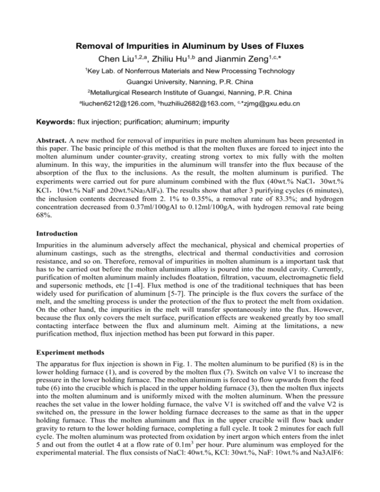
Removal of Impurities in Aluminum by Uses of Fluxes Chen Liu1,2,a, Zhiliu Hu1,b and Jianmin Zeng1,c,* 1 Key Lab. of Nonferrous Materials and New Processing Technology Guangxi University, Nanning, P.R. China 2 Metallurgical Research Institute of Guangxi, Nanning, P.R. China a liuchen6212@126.com, bhuzhiliu2682@163.com, c,*zjmg@gxu.edu.cn Keywords: flux injection; purification; aluminum; impurity Abstract. A new method for removal of impurities in pure molten aluminum has been presented in this paper. The basic principle of this method is that the molten fluxes are forced to inject into the molten aluminum under counter-gravity, creating strong vortex to mix fully with the molten aluminum. In this way, the impurities in the aluminum will transfer into the flux because of the absorption of the flux to the inclusions. As the result, the molten aluminum is purified. The experiments were carried out for pure aluminum combined with the flux (40wt.% NaCl,30wt.% KCl,10wt.% NaF and 20wt.%Na3AlF6). The results show that after 3 purifying cycles (6 minutes), the inclusion contents decreased from 2. 1% to 0.35%, a removal rate of 83.3%; and hydrogen concentration decreased from 0.37ml/100gAl to 0.12ml/100gA, with hydrogen removal rate being 68%. Introduction Impurities in the aluminum adversely affect the mechanical, physical and chemical properties of aluminum castings, such as the strengths, electrical and thermal conductivities and corrosion resistance, and so on. Therefore, removal of impurities in molten aluminum is a important task that has to be carried out before the molten aluminum alloy is poured into the mould cavity. Currently, purification of molten aluminum mainly includes floatation, filtration, vacuum, electromagnetic field and supersonic methods, etc [1-4]. Flux method is one of the traditional techniques that has been widely used for purification of aluminum [5-7]. The principle is the flux covers the surface of the melt, and the smelting process is under the protection of the flux to protect the melt from oxidation. On the other hand, the impurities in the melt will transfer spontaneously into the flux. However, because the flux only covers the melt surface, purification effects are weakened greatly by too small contacting interface between the flux and aluminum melt. Aiming at the limitations, a new purification method, flux injection method has been put forward in this paper. Experiment methods The apparatus for flux injection is shown in Fig. 1. The molten aluminum to be purified (8) is in the lower holding furnace (1), and is covered by the molten flux (7). Switch on valve V1 to increase the pressure in the lower holding furnace. The molten aluminum is forced to flow upwards from the feed tube (6) into the crucible which is placed in the upper holding furnace (3), then the molten flux injects into the molten aluminum and is uniformly mixed with the molten aluminum. When the pressure reaches the set value in the lower holding furnace, the valve V1 is switched off and the valve V2 is switched on, the pressure in the lower holding furnace decreases to the same as that in the upper holding furnace. Thus the molten aluminum and flux in the upper crucible will flow back under gravity to return to the lower holding furnace, completing a full cycle. It took 2 minutes for each full cycle. The molten aluminum was protected from oxidation by inert argon which enters from the inlet 5 and out from the outlet 4 at a flow rate of 0.1m3 per hour. Pure aluminum was employed for the experimental material. The flux consists of NaCl: 40wt.%, KCl: 30wt.%, NaF: 10wt.% and Na3AlF6: 20wt.%. The detection of inclusions was conducted based on image analysis technique that had been developed by our researching group [8]. Fig. 1 Schematic sketch of flux injetion apparatus Hyscan II hydrogen analyzer by BNF Metals Technology Centre for the UK Light Metal Founders Association was used for measurement of hydrogen concentration, as shown in Fig. 2. A constant mass of the melt (approximately 100g) is placed in a chamber and the pressure reduced rapidly to a predetermined value by a vacuum pump. The chamber and associated vacuum system is then isolated from the pump and the sample allowed to solidify. As the melt cools hydrogen is released and its partial pressure is measured by a calibrated Pirani gauge whose output is converted continuously to a digital display of hydrogen contents. V3 PIRANi TRAP V1 V2 SAMPLE CHAMBER VACUUM PUMP Fig. 2 Schematic sketch of hydrogen content tester The experimental results The influences of flux injection on the hydrogen contents. The alloy was smelted at an IF furnace and the molten aluminum was transferred into the lower holding furnace to adjust the temperature. Flux injection was carried out at 730℃, and the samples were taken from the crucible to measure contents of hydrogen after each cycle. The measurements were repeated 5 times for one full cycle. 4 experimental cycles were carried out and 20 measurements were done. The morphology of cross sections of the samples was shown in Fig. 3. It is clear that the porous honeycomb-like morphology on the cross section indicates higher hydrogen content due to the precipitation of the hydrogen during solidification of the samples. The precipitating pressure of hydrogen Pg can be expressed by the following equation [9]: Pg [ C0 ]2 ks f s (t ) kl (1 f s (t )) (1) where, C0 is initial hydrogen content in the molten aluminum; fs(t) and fl(t) are solid and liquid fraction, respectively, both of which are functions of solidification time; kS and kl are the coefficients of solubility of hydrogen in the molten aluminum, respectively. The equation (1) indicates that the precipitation pressure is direct proportional to the squire of hydrogen content and the precipitation pressure increases with the proceeding of solidification. Therefore, the pressure will be large enough to overcome the surface tension of the melt to form porosity in the solidifying casting. As the Fig.3 shows, hydrogen contents reduce as the flux injection time increases. The hydrogen concentration decreased from 0.37ml/100gAl (3a) to 0.12ml/100gAl (3d) after three cycles (6 minutes), with hydrogen removal rate being 68%. (a) (b) (c) (d) Fig.3 The section of samples before and after purification: (a) no treatment; (b) after treatment 2 min; (c) after treatment 4 min; (d) after treatment 6 min The influences of fluxes on the inclusion contents. The impurity contents before and after the treatment were seen in Table 1. It could be seen that average impurity content reduced from 2.1% before treatment to 0.33% after treatment, a removal rate of 83.3%. The impurities in the aluminum mainly include aluminum oxide and dross that may originates from dirty tools, sand and other molding debris, sludge and the oxidation of alloying elements. The most notable impurity in the melt is the oxides which is formed through the chemical reaction between water and aluminum. It is dispersedly distributed in the melt and usually of small size (from less than 1 to hundreds of micron and of flocculent structures), which is extremely harmful to the properties of the materials. Table. 1 The impurity content before and after flux ejection treatment Heat No. No treatment After treatment J1 J2 J3 J4 J5 average 2.1 1.8 2.4 1.9 2.0 2.1 0.37 0.33 0.40 0.26 0.38 0.35 Inclusion removal ratio [wt%] 83.3 Conclusions Flux injection technology has been presented in this paper. The flux and the aluminum melt can be mixed fully by driving the flux to inject the melt against gravity under the function of the pressure differential between the melt and the flux. The experiments were carried out for pure aluminum with the flux (40wt.% NaCl, 30wt.% KCl, 10wt.% NaF and 20wt.%NA3AlF6). The results show that after 3 cycles (6 minutes), the impurity contents decrease from 2.1% to 0.35%, a removal rate of 83.3%; and hydrogen concentrations reduce from 0.37ml/100gAl to 0.12ml/100gAl, a hydrogen removal rate of 68%. The industrial research has been under way. Acknowledgements The authors sincerely thank the financial supports from Chinese 973 pre-project (No: 2009CB626602). References [1] [2] [3] [4] [5] [6] [7] [8] [9] Sahai Y., Guthrie R, Hydrodynamics of gas stirred melts: Part I. Gas/liquid coupling, Metall. Mater. Trans. B. 13 (1982) 193-202. Apelian D., Mutharasan T, Modeling of inclusion removal in melt sysytems, 72nd annual IACHE Meeting. (1979) 26-36. Sigworth G. K., Engh T. A, Chemical and kinetic factors related to hydrogen removal from aluminum, Metall. Trans. B. 13 (1982) 447-460. Li K., Wang J. and Shu D, Theoretical and experimental investigation of aluminum melt cleaning using alternating electromagnetic field, Mater. Lett. 56 (2002) 215-220. Storchai E. I., Savel'eva V. M. and Kukolev E. N, Kinetics of fluxing aluminum alloys in chloride-fluoride melts. Chem. Petr. Eng. 9 (1973) 841-843. A. Silny and T.A. Utigard, Light Metals 1997, ed. R. Huglen (Warrendale, PA: TMS). (1997) 871–878. D.V. Neff and B.P. Cochran, Light Metals 1993, ed. S.K. Das (Warrendale, PA: TMS). (1993) 1053–1060. W.C. Wang, Z.B. Xu, J.H. Pan and J.M.Zeng, A study on morphology and detection of inclusion in Al-12Si casting alloy, in: G.C.Sih, S.T.Tu and Z.D.Wang (Eds.), Transferability and applicability of current mechanics approches, East China University of Science and Technology Press, Shanghai, 2009, pp. 489-494. J.M. Zeng, Yaohe Zhou, A New Sand Casting Process with Accelerated Solidification Rate, Materials Science Forum. 686 (2011) 765-769

