Assignment 4 – Boundary representation
advertisement
ASSIGNMENT 4 – BOUNDARY REPRESENTATION
Summary
In this assignment a boundary representation (B-rep) will be used in order to create,
manipulate, query and visualize solid objects.
Objectives
At the end of this assignment you will:
be able to describe the structure of a B-rep;
be acquainted with typical operations on a B-rep (traversal, query, etc.)
provided by a geometric kernel;
have insight into the Euler-Poincaré invariant.
Suggested references
ACIS Documentation: graphics.tudelft.nl/~in4003/acis16
Information on Euler-Poincaré invariant:
http://www.cs.mtu.edu/~shene/COURSES/cs3621/NOTES/model/euler.html
1.1 Introduction
Basically, in this assignment you will build an application able to create two solid primitives,
issue a set operation between them, and finally query the resulting solid model in various
ways. For this, you will use the commercial geometric kernel ACIS and, in particular, its
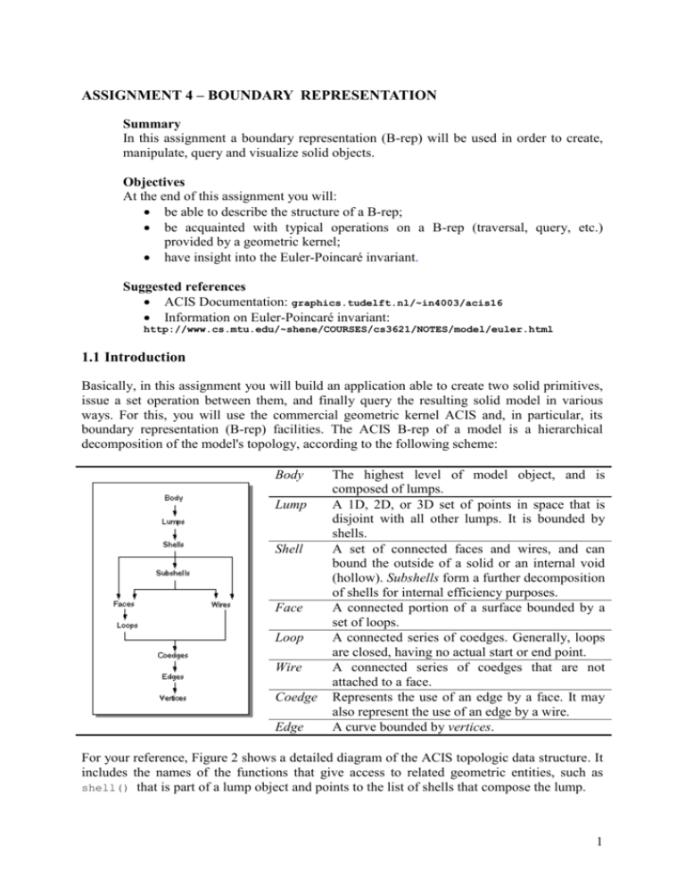
boundary representation (B-rep) facilities. The ACIS B-rep of a model is a hierarchical
decomposition of the model's topology, according to the following scheme:
Body
Lump
Shell
Face
Loop
Wire
Coedge
Edge
The highest level of model object, and is
composed of lumps.
A 1D, 2D, or 3D set of points in space that is
disjoint with all other lumps. It is bounded by
shells.
A set of connected faces and wires, and can
bound the outside of a solid or an internal void
(hollow). Subshells form a further decomposition
of shells for internal efficiency purposes.
A connected portion of a surface bounded by a
set of loops.
A connected series of coedges. Generally, loops
are closed, having no actual start or end point.
A connected series of coedges that are not
attached to a face.
Represents the use of an edge by a face. It may
also represent the use of an edge by a wire.
A curve bounded by vertices.
For your reference, Figure 2 shows a detailed diagram of the ACIS topologic data structure. It
includes the names of the functions that give access to related geometric entities, such as
shell() that is part of a lump object and points to the list of shells that compose the lump.
1
Figure 1. Relations among ACIS entities
1.2 The test program
As you will see, this will end up being much easier than the similar 2D tasks in Assignment 3,
mainly because (i) the geometric kernel ACIS already provides you with many powerful
operations and methods, and (ii) the application framework you are given already implements
much of the functionality required.
This is how your final application will work:
1. With the 'Create' menu, the user issues the creation of two solid primitives (see Figure
2.a), which will be immediately visualized at the left-hand pane of the application. The
user can then modify their relative position.
2. Next, with the 'Tool' menu, the user chooses a set operation to be performed between
the two primitives created above (see Figure 2.b). The result will be immediately
visualized at the right-hand pane of the application (see Figure 2.c).
3. Once the set operation has been performed, the user can create again a single primitive
and combine this through a set operation with the previous result. This way, simple
models can be constructed through the repeated addition of primitives.
4. Finally, using the 'Query' menu, the user can issue a number of topologic queries on an
entity that is to be selected at the right-hand pane (see Figure 2.d).
2
(a)
(b)
(c)
(d)
Figure 2. Interface of the application
Setting up the environment
Before you can compile the program and test your code, you need to check that the right
library paths are set. In your Visual Studio 2002, go to menu ‘Tools->Options->Projects>VC++ Directories’ to open the options property page (see Figure 3).
Figure 3: Setting directory paths
To correctly set the include (header) files, ensure the drop-down list “Show directories for” is
set to
3
a) Include files: C:\program files\acis16\include (see Figure 3)
b) Library files: C:\program files\acis16\lib\NT_DLL; C:\program
files\acis16\bin\NT_DLL
Click the ‘OK’ button to apply the settings. To execute the program, select menu item
‘Debug->Start without debugging’.
1.3 Programming tasks
This section sums up the task sequence for this assignment. All sources required are to be
found in directory H:\brep, file Brep.cpp.
Task 1: creating primitives
Implement the methods
create_cuboid
create_cylinder
create_sphere
create_hexagonal_prism
create_triangular_prism
by calling the corresponding ACIS API functions and returning the desired primitives.
These methods are called from the 'Create' menu of your application. The empty methods
all look like this:
outcome create_cuboid ( BODY*& cuboid )
{
}
Make sure you pass the result to the variable in the function argument, e.g. <cuboid> in
‘create_cuboid’ function, and return its 'outcome'.
Task 2: Boolean operations
Complex shapes can be created by combining primitives using the Boolean operations:
union, intersection and subtraction. Implement the methods
A_union_B
A_intersection_B
A_subtraction_B
using appropriate ACIS API functions, within the methods, on the parameters passed as
arguments. These methods are called from the 'Tools' menu of your application. The
empty methods look like this:
outcome A_union_B ( BODY* solidA, BODY* solidB, BODY*& result )
{
}
When implemented it should be possible to combine the solids in the left viewing pane by
applying a Boolean operation from the menu.
4
Task 3: querying
Implement the following two queries:
3a) given a face that has been selected by the user, highlight all its neighboring faces. The
method you should complete, looks like this:
void query_face (FACE* face_subject)
{
}
The parameter face_subject is a pointer the highlighted face. Find the pointers to all the
adjacent faces and call the function redraw_entity (FACE* entity) for each of them.
3b) given a body that has been selected by the user, determine the amount of vertices (V),
edges (E), faces (F), shells (S) and rings (R). These are all quantities in the formula for
the Euler-Poincaré invariant, that we will verify in a moment.
NB: R = number of (face) loops – 1.
The method you should complete, looks like this:
void query_body (BODY* body_subject, char results_text [ 256 ])
{
}
The parameter body_subject is a pointer to the body that is to be queried. The parameter
results_text contains a string of characters that describes the result of the query.
1.4 Verification
Finally, you are going to build a model that makes it easy to verify that all programming tasks
were performed correctly. Additionally, we will be verifying the Euler-Poincaré invariant and
gain some understanding in how the geometric kernel ACIS represents geometry.
Step 1: constructing a simple model
Recreate the model from Figure 3. The hexagonal hole should go completely through the
house. You will need to add some code to perform the required transformations, e.g. scale,
rotate and translate.
Figure 4: Model of a house
5
Make sure that your model is topologically equivalent to the model in Figure 3, for
instance the ‘roof’ should not stick out at the front of the ‘house’. The empty method, to
be complete completed by you, looks like this:
outcome create_model ( BODY*& result_model )
{
}
You should pass the final result of the model to <result_model>. The method is called
from the 'Tools->CreateModel' menu of your application.
Step 2: verifying the Euler-Poincaré invariant
The formula for the Euler-Poincaré invariant can be written as:
V – E + F – R – 2*S = 2 * G.
Here G stand for the genus, which intuitively is ‘the number of holes’ in the object. For
our example model from Figure 3, we have G = 1.
Check that the invariant holds for the model from Figure 3 by performing a query on the
body.
Try to count for yourself and see if the numbers you find agree with those returned by the
query. Can you understand the results?
Hint: perform queries on each of the primitives and find out how they individually
conform to the Euler invariant.
6
