PSoC 4 Lab 1 – Blinking LED – Lab Manual
advertisement

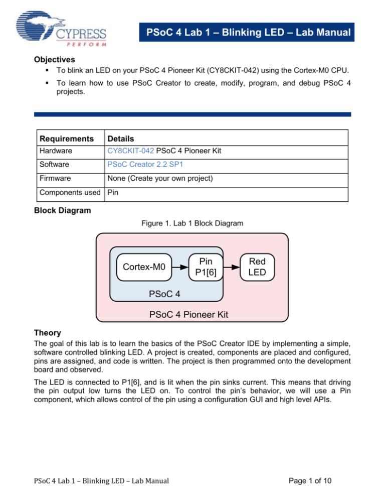
PSoC 4 Lab 1 – Blinking LED – Lab Manual Objectives To blink an LED on your PSoC 4 Pioneer Kit (CY8CKIT-042) using the Cortex-M0 CPU. To learn how to use PSoC Creator to create, modify, program, and debug PSoC 4 projects. Requirements Details Hardware CY8CKIT-042 PSoC 4 Pioneer Kit Software PSoC Creator 2.2 SP1 Firmware None (Create your own project) Components used Pin Block Diagram Figure 1. Lab 1 Block Diagram Cortex-M0 Pin P1[6] Red LED PSoC 4 PSoC 4 Pioneer Kit Theory The goal of this lab is to learn the basics of the PSoC Creator IDE by implementing a simple, software controlled blinking LED. A project is created, components are placed and configured, pins are assigned, and code is written. The project is then programmed onto the development board and observed. The LED is connected to P1[6], and is lit when the pin sinks current. This means that driving the pin output low turns the LED on. To control the pin’s behavior, we will use a Pin component, which allows control of the pin using a configuration GUI and high level APIs. PSoC 4 Lab 1 – Blinking LED – Lab Manual Page 1 of 10 PSoC 4 Lab 1 – Blinking LED – Lab Manual Procedure – Firmware 1) Open PSoC Creator. It is located in the Cypress -> PSoC Creator folder in the Windows start menu. 2) Create a new project by using the “New->Project” option in the “File” Menu. This step is shown in Figure 2. Figure 2. PSoC Creator Project Creation 3) The “New Project” dialog will appear. Click on the “Empty PSoC 4 *CY8C42*) Design” option under “Empty Templates”. This step is shown in Figure 3. 4) Set the name of the project “Lab 1 Blink” or something similar. Click “OK” to create the project. Figure 3. PSoC Creator “New Project” Dialog PSoC 4 Lab 1 – Blinking LED – Lab Manual Page 2 of 10 PSoC 4 Lab 1 – Blinking LED – Lab Manual 5) You will then be taken to the PSoC Creator project schematic. The right hand side of the PSoC Creator IDE will show the component catalog. Select the “Digital Output Pin” component from the “Ports and Pins” category, and drag it into your schematic. This step is shown in Figure 4. Figure 4. Adding a Digital Output Pin PSoC 4 Lab 1 – Blinking LED – Lab Manual Page 3 of 10 PSoC 4 Lab 1 – Blinking LED – Lab Manual 6) Double-click the pin component to configure it using its customizer. In the customizer, rename the pin to “Pin_Red”, and unselect the “HW Connection” checkbox to allow us to control it in software. Click OK to apply changes and close the customizer. This step is shown in Figure 5. Figure 5. Pin Configuration Customizer PSoC 4 Lab 1 – Blinking LED – Lab Manual Page 4 of 10 PSoC 4 Lab 1 – Blinking LED – Lab Manual 7) On the left-hand side of the PSoC Creator IDE is the “Workspace Explorer”, which shows the files contained within the PSoC Creator project. Double click on the “Lab 1 Blink.cydwr” file to open the design wide resources interface. This interface configures aspects of the project that affect the entire part, such as pin mapping, clocks, and interrupts. This step is shown in Figure 6. Figure 6. Design Wide Resources - Pins 8) The “Pins” tab of the Design Wide Resources will be opened by default. Click the dropdown under the “Port” column, and map the “Pin_Red” pin to P1[6]. This step is shown in Figure 7. Figure 7. Pin Selection Interface PSoC 4 Lab 1 – Blinking LED – Lab Manual Page 5 of 10 PSoC 4 Lab 1 – Blinking LED – Lab Manual 9) In the “Workspace Explorer”, double-click the “main.c” file to open it in the code editor. This step is shown in Figure 8. Figure 8. PSoC Creator Code Editor Showing main.c Code 10) Add the code shown in Code 1 inside the “for(;;)” loop to toggle the LED pin once every half second. Code 1. Lab 1 Pin Toggle Code Pin_Red_Write(~Pin_Red_Read()); CyDelay(500); 11) Press the “Program” button on the PSoC Creator toolbar to build the project and program your kit. This step is shown in Figure 9. The results of the build and program operation will appear in the “Output” area at the bottom of the PSoC Creator GUI. This is shown in Figure 11. At this point, the red LED on the kit should start blinking at a 1 Hz rate, at 50% duty cycle. PSoC 4 Lab 1 – Blinking LED – Lab Manual Page 6 of 10 PSoC 4 Lab 1 – Blinking LED – Lab Manual Figure 9a. PSoC Creator “Program” Button Note – the first time you plug in your PSoC 4 Pioneer Kit to your computer, it will enumerate over USB and link with the correct drivers (the drivers get installed with the kit installer). This enumeration and driver scanning process may take a few moments, just like with any other USB device. You may also see a pop-up window inside PSoC Creator, asking you to confirm which device to program (‘Select Debug Target’). Simply chose the “KitProg”, the PSoC 4 Pioneer kit as shown below, and then press “Connect”. Figure 10b. PSoC Creator “Select Debug Target” Window PSoC 4 Lab 1 – Blinking LED – Lab Manual Page 7 of 10 PSoC 4 Lab 1 – Blinking LED – Lab Manual Figure 11. PSoC Creator Output Window Procedure – CY8CKIT-042 Hardware Setup 12) No hardware setup is required for this project. The red LED cathode is connected to P1[6] with a copper trace. Conclusion The red LED D9 is blinking on your PSoC 4 Pioneer Kit at a rate of 1 Hz and a duty cycle of 50%. PSoC 4 Lab 1 – Blinking LED – Lab Manual Page 8 of 10 PSoC 4 Lab 1 – Blinking LED – Lab Manual Stretch Goals Change the delay to change the LED blink rate. o We have defined the delay between writes as 500 milliseconds. This results in blinking at 1 Hz. o Try increasing or decreasing the delay as a constant or variable to change the blink rate at design time or at run-time. Change the LED pin to drive the other colors. o We are driving the red LED out of the tri-color array using P1[6]. The green LED is attached to P0[2]. The blue LED is attached to P0[3]. Remember that all 3 LEDs are active low, and that driving the pins low will turn them on. o Try driving these other LEDs instead of, or along with the red LED. Use the debugger to step through code execution. o PSoC Creator has a built-in debugger that works with the KIT-042 as well as the stand-alone MiniProg 3. o Start debugging by pressing the “debug” icon on the PSoC Creator toolbars. o Place a breakpoint on the “Pin_Red_Write…” line by clicking in the code editor to the left of the line. o Step through the loop and observe the LED state changing. PSoC 4 Lab 1 – Blinking LED – Lab Manual Page 9 of 10 PSoC 4 Lab 1 – Blinking LED – Lab Manual Document Revision History Revision By Description 01 MAXK First Release PSoC 4 Lab 1 – Blinking LED – Lab Manual Page 10 of 10


