Related topics Ultrasonic transmission measurement, propagation of
Shear waves in solid-state materials
TEAS
1.6.09
-00
Related topics
Ultrasonic transmission measurement, propagation of ultrasound waves, ultrasound wave modes, shear waves, longitudinal and transverse waves, modulus of elasticity, and sound velocity
Principle
The aim of this experiment is to study the generation and propagation of ultrasound waves in solid objects. In addition, the additional generation of transverse wave modes (shear wave modes) resulting from an oblique angle of incidence should be identified and the sound velocities for the longitudinal and transverse component should be determined. The relationship between the coefficients of elasticity of the material and its sound velocities enables the determination of the magnitude of the coefficients.
Equipment
1 Basic Set Ultrasonic echoscope consisting of:
1x Ultrasonic echoscope
1x Ultrasonic probe 1 MHz
1x Ultrasonic probe 2 MHz
1x Ultrasonic test block
1x Ultrasonic cylinder set
1x Ultrasonic test plates
1x Ultrasonic gel
1 Extension set: Shear waves consisting of:
1x Ultrasonic probe 1 MHz
1x Shear wave set (incl. 2 probe holders)
1x Aluminium sample for shear waves
1x Hydrophone for sound field measurement
1x Hydrophone plate
1x Hydrophone holder
1x Holder block and
PC with a USB port + measurement software
13921-99
13921-03
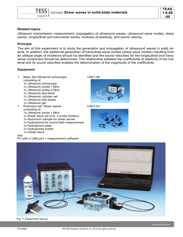
Fig. 1: Experiment set-up
P5160900 www.phywe.com
PHYWE Systeme GmbH & Co. KG © All rights reserved
TEAS
1.6.09
-00
Shear waves in solid-state materials
Task:
1. Determine the sound amplitude of an ultrasound wave passing through an acrylic glass plate
(transmission measurement) as a function of the angle of incidence for the longitudinal and transverse component.
2. Use the measurement curves to determine the longitudinal sound velocity in acrylic glass based on the angle of the total reflection, and the transverse sound velocity based on the amplitude maximums and the angle of the total reflection.
3. Determine the sound amplitude of an ultrasound wave passing through an aluminium plate
(transmission measurement) as a function of the angle of incidence for the longitudinal and transverse component.
4. Use the measurement curves to determine the longitudinal sound velocity in aluminium, based on the angle of the total reflection, and the transverse sound velocity based on the angle of the amplitude maximums and the angle of the total reflection.
5. Based on the transverse and longitudinal sound velocities, calculate the coefficient of elasticity for acrylic glass and aluminium.
Set-up and procedure
Figure 1 shows the experiment set-up.
The experiment requires an echoscope, a PC with the measurement software installed, and a port for connecting the echoscope (USB), two ultrasonic probes (2 MHz), and the shear wave set.
Set-up of the shear wave set
Figure 2 is a schematic representation of the shear wave set. The shear wave sets comprises a tray, two probe holders, and the test specimens with an angle scale (material: acrylic glass and aluminium).
The ultrasonic probes are fastened in the probe holders and coupled to the tray with a pea-sized amount of ultrasound gel.
Fig. 2: Schematic set-up with an indication of the angular positions
2 PHYWE Systeme GmbH & Co. KG © All rights reserved P5160900
Shear waves in solid-state materials
TEAS
1.6.09
-00
Note: The probes must be coupled to the tray without any bubbles. To do so, press the probes against the tray and remove the air between the probes and the tray by moving the probes to and fro. As a result, the probe surface appears on the inside of the tray as a homogeneous unit (see Fig. 3).
Attention : After the shear wave set has been used, clean the probes and tray in order to remove any residual ultrasound gel. Use some water or soap solution and a soft cloth (paper). Do not use alcohol or other solvent-containing cleaning agents.
Fig. 3: Poor coupling (left) and good, air-free coupling (right)
Connecting the equipment
Connect the ultrasonic echoscope to a free USB port of your computer with the aid of a USB cable. If the software has been installed correctly, the device will be automatically identified.
Connect the ultrasonic probes to the sockets PROBE (Reflection) = Receiver and PROBE (Transmission) = Transmitter. The set-up is as shown in Figure 2. The switch must be set to TRANS (transmission measurement).
Software:
The software is used for recording, displaying, and evaluating the data. After the start of the software, the device and interface will be identified automatically. The main screen with the A-scan signal in the upper area and the TGC in the lower area will be displayed. The frequency of the receiver probe and the device settings (gain, transmitting power, reflection/transmission) will also be displayed. The measurement cursors can be moved with the mouse and the amplitude and time of flight can then be read.
Switch the software to Amp = amplitude representation. Select the settings for the gain and transmission power so that the signals for the perpendicular passage through the plates do not overshoot but also that they are as high as possible. Ensure that the gain settings remain identical in order to be able to compare the amplitude measurements.
Attention: Please observe the special operating and safety instructions in the instruction manuals of the ultrasonic echoscope.
Execution of the experiment
If at all possible, the tray should be filled with degassed water (approximately 850 ml). If degassed water is unavailable, any potential air bubbles must be removed from the area in front of the probes since they affect the measurement amplitude. Couple the probes to the tray as de scribed in the section “Set-up of the shear wave set”.
The two probes face each other. For the exact alignment of the probes, set the echoscope to the trans-
P5160900 www.phywe.com
PHYWE Systeme GmbH & Co. KG © All rights reserved
TEAS
1.6.09
-00
Shear waves in solid-state materials mission mode and adjust a maximum signal by moving the probes. Then, position the material specimen in the middle between the probes (see Figure 2), i.e. in the sound beam, and align it perpendicularly to the sound axis until the maximum signal amplitude is reached. Adjust the maximum (non-overshooting) signal amplitude with the aid of the transmission and reception gain. TGC must not be used (all of the controllers turned to the left stop) since the time of flight of the signal varies during the experiment. If the perpendicular alignment is good, the multiple reflexes are particularly distinct (Figure 4 shows the result for aluminium) = maximum setting. This is the 0° measurement position (see Figure 10, left). Any possible deviations from the 0° position of the scale must be added or subtracted for later measurements. The angle of rotation, which is referred to the maximum setting, must be measured.
Fig. 4: Transmission signal of a perpendicular sound transmission through an aluminium plate with multiple reflections in the plate (circle)
The maximum amplitude of the transmission pulse is determined with the aid of the measurement cursor. We recommend using the time and amplitude zoom feature of the software in order to be able to measure even small amplitudes with a high level of precision (Fig. 5).
4 PHYWE Systeme GmbH & Co. KG © All rights reserved P5160900
Shear waves in solid-state materials
TEAS
1.6.09
-00
Fig. 5: Zoomed transmission signal
In the 0°-position (perpendicular incidence of the sound wave), only one echo is generated by the longitudinal component. When the material specimen is turned, the amplitude of the longitudinal sound wave in turn decreases.
P5160900 www.phywe.com
PHYWE Systeme GmbH & Co. KG © All rights reserved
TEAS
1.6.09
-00
Shear waves in solid-state materials
Fig. 6: Aluminium s pecimen at 10° with a longitudinal (circle) and transverse component (rectangular) (upper image) and the acrylic glass specimen at 27.5° (lower image)
At bigger angles, the longitudinal component disappears completely and there are only transverse components. Since the transverse sound velocity is smaller than the longitudinal one, the individual components can be distinguished rather well based on their difference in time of flight.
6 PHYWE Systeme GmbH & Co. KG © All rights reserved P5160900
Shear waves in solid-state materials
TEAS
1.6.09
-00
Fig. 7: Aluminium specimen at 15° with only a transverse component (upper image) and the acrylic glass specimen at 35°
(lower image)
When the specimen is turned even further, the amplitude of the transverse component reaches a maximum before it decreases again until it also disappears completely when the total reflection angle is reached (provided that this is the case).
P5160900 www.phywe.com
PHYWE Systeme GmbH & Co. KG © All rights reserved
TEAS
1.6.09
-00
Shear waves in solid-state materials
Fig. 8: Aluminium specimen at 20° with a maximum of the transverse component
Fig. 9: Aluminium specimen at 27.5° - the transverse component has nearly disappeared
The transmission amplitudes of the longitudinal and transverse sound waves are measured for various different angles of incidence at small intervals (in steps of 2.5° beginning with the perpendicular incidence until a signal can no longer be measured). For all of the angle settings, the maximum signal amplitude is measured for the longitudinal as well as for the transverse (shear) wave. During the measurement, the transmission and reception gain as well as the coupling of the probes must be kept constant.
Note: In the software, average values can be calculated under Parameter-Scan Average in order to min-
8 PHYWE Systeme GmbH & Co. KG © All rights reserved P5160900
Shear waves in solid-state materials imise the variations during the amplitude determination.
Theory and calculations
TEAS
1.6.09
-00
Fig. 10: Schematic representation of the measurements at 0° (with reflections) and 30° (without reflections)
In the liquid, only longitudinal ultrasound waves with measurable amplitude can propagate. When they hit the surface, parts of the sound wave penetrate the solid object while the other parts are reflected. The coefficient of reflection and the coefficient of transmission are determined by the differences in impedance between the liquid and solid body (Fig. 10, left).
An ultrasound wave that hits a surface through a liquid at an angle produces shearing forces. The shear wave propagates inside the solid body. At the opposite side, it partly leaves the solid body again in the form of a longitudinal sound wave (Fig. 10 right). In the case of a plane-parallel plate, the angle of emergence equals the angle of incidence into the plate (
). In accordance with the law of refraction (1), the path of the sound in the plate results from the ratio between the sound velocity in the liquid c
Fl
and the sound velocity in the solid object (c
L
= longitudinal sound velocity; c
T
= transverse sound velocity).
Law of refraction: sin
(1) sin
(
(
L
)
)
c
FL c
L
; sin (
) sin (
T
)
c
FL c
T
The shear wave reaches its maximum [V.A.Sutilov, Physik des Ultraschalls, Akademie-Verlag Berlin,
1984, page 228] at an angle of refraction
T of 45°. Based on this angle, equation (2) can be used to determine the transverse sound velocity.
(2) c
T
1 / 2 sin ( ß
T
) c
F L
If the sound velocity is higher in the solid body than in the liquid, total reflection occurs as of a certain
P5160900 www.phywe.com
PHYWE Systeme GmbH & Co. KG © All rights reserved
TEAS
1.6.09
-00
Shear waves in solid-state materials angle
. If one determines this angle, the sound velocity in the solid body can be calculated with the aid of equation (3).
(3) c
L
1 sin (
L
) c
FL
; c
T
sin
1
(
T
) c
FL
Based on the sound velocities that were determined for the longitudinal (c
T
) and transverse component
(c
T
), the coefficients of elasticity of the material can be determined with the aid of equations (4) to (6) (E
= modulus of elasticity; G = shear modulus; µ = Poisson’s ratio).
(4) c c
L
T
2 ( 1
)
1
2
(5) c
T
G
(6) c
L
E
( 1
)
( 1
( 1
)
2
)
For the evaluation of the measurement curves (transmission amplitude A as a function of the angle of rotation
), the angle of the total reflection can be determined by extrapolation and based on equation (7):
(7) A (
)
A (
2
2
)
A
1
(
1
)
(
1
)
A (
1
)
A(
1
) and A(
2
) are the amplitude values of two measurements. If A(
)=0, the angle of the total reflection results.
10 PHYWE Systeme GmbH & Co. KG © All rights reserved P5160900
Shear waves in solid-state materials
TEAS
1.6.09
-00
Results
The transverse wave amplitude is measured only at angles without a longitudinal component in order to avoid superimposition effects. At angles abo ve 80°, the complete sound incidence to the plate can no longer be guaranteed.
Table 1: Measurement values - acrylic glass specimen
Material: acrylic glass
Longitudinal Transverse Longitudinal Transverse
Angle of incidence Amplitude Amplitude Angle of incidence Amplitude Amplitude
17.5
20
22.5
25
27.5
30
32.5
35
37.5
40
0
2.5
5
7.5
10
12.5
15
924
921
912
889
867
823
784
732
651
533
381
209
91
11 144
382
500
513
40
42.5
45
47.5
50
52.5
55
57.5
60
62.5
65
67.5
70
72.5
75
77.5
80
392
373
339
311
280
239
200
153
108
80
513
502
492
476
457
433
418
Transmissionsmessung Polyacryl
1000
900
800
700
600
500
400
300
200
100
0
0 5 10 15 20 25 30 35 40 45 50
Drehwinkel [°]
55 60 65 70 75 80 85 longitudinal transversal
Fig. 11: Transmission amplitude as a function of the angle of rotation - acrylic glass specimen
P5160900 www.phywe.com
PHYWE Systeme GmbH & Co. KG © All rights reserved
TEAS
1.6.09
-00
Shear waves in solid-state materials
Table 2: Measurement values – aluminium specimen
Material: aluminium
Longitudinal Transverse
Angle of incidence Amplitude Amplitude
0 703
2.5
5
700
671
7.5
10
12.5
15
587
307
140
494
17.5
20
22.5
25
27.5
835
872
688
312
88
Transmissionsmessung Aluminium
1000
900
800
700
600
500
400
300
200
100
0
0 2 4 6 8 10 12 14 16 18
Drehwinkel [°]
20 22 24 26 28 30 longitudinal transversal
Fig. 12: Transmission amplitude as a function of the angle of rotation
– aluminium specimen
12 PHYWE Systeme GmbH & Co. KG © All rights reserved P5160900
Shear waves in solid-state materials
TEAS
1.6.09
-00
Based on the diagrams, the angles of total reflection are determined by an extrapolation with regard to the baseline (equation (7)). The angles of the maximum transverse amplitude are determined graphically based on the measurement diagrams.
Table 3: Angles of total reflection and of the shear wave maximums
Acrylic glass
Aluminium
Total reflection, longitudinal
32.8°
14.6°
Total reflection, transverse
87.1
°
28.5°
Maximum, transverse
38.8°
19.0°
Based on the angle of total reflection of the longitudinal wave and based on the angle of the maximum amplitude of the transverse wave, the sound velocities are determined with the aid of the equations (2) and (3). The sound velocity of water of 1480 m/s is used for the calculation.
Table 4: Calculated sound velocities
Acrylic glass
Aluminium
Literature values for comparison:
Total reflection, longitudinal
2729 m/s
5873 m/s
Total reflection, transverse
1482 m/s
3103 m/s
Maximum, transverse
1670 m/s
3214 m/s
Aluminium: c
L
=6320-6420 m/s, c
T
=3040-3160 m/s
Acrylic glass: c
L
=2610-2780 m/s, c
T
=1430-1450 m/s
The deviations from the literature values as well as the deviations between the total reflection and maximum measurements are mainly due to the beam displacement (receiver transducer not in the maximum) and to the attenuation in the material.
The sound velocities in Table 4 can be used to calculate the coefficients of elasticity based on equations
(4) to (6).
The following densities are used:
(acrylic glass) = 1.2 g/cm³;
(alu minium) = 2.7 g/cm³.
For the transverse sound velocity, the value of the total reflection is used.
Table 5: Coefficients of elasticity
E [MPa] G [MPa] µ
Acrylic glass 6800 2600
Aluminium 68000 26000
0.29
0.31
P5160900 www.phywe.com
PHYWE Systeme GmbH & Co. KG © All rights reserved
TEAS
1.6.09
-00
Shear waves in solid-state materials
14 PHYWE Systeme GmbH & Co. KG © All rights reserved P5160900
![List of changes: 1- Page2: reference “[22]” is added to the end of this](http://s3.studylib.net/store/data/007188902_1-dc3ffc6bfa98d4af9207cb70e1033027-300x300.png)

