Sonoma Valley Treatment Plant Detailed Virtual Tour
advertisement
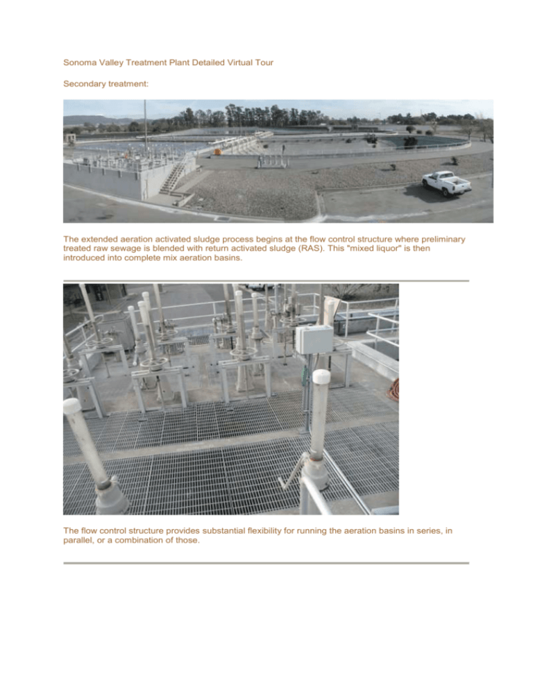
Sonoma Valley Treatment Plant Detailed Virtual Tour Secondary treatment: The extended aeration activated sludge process begins at the flow control structure where preliminary treated raw sewage is blended with return activated sludge (RAS). This "mixed liquor" is then introduced into complete mix aeration basins. The flow control structure provides substantial flexibility for running the aeration basins in series, in parallel, or a combination of those. This is the RAS channel in the flow control structure. As you can see, the secondary clarifiers do an excellent job of thickening the RAS, which often concentrates up to 20,000 mg/L. An infrared optical probe is used in the RAS channel to track the RAS suspended solids on the plant's SCADA system. As seen in this empty aeration basin, fine bubble tube-style diffusers are used. The diurnal plant influent flow is equalized within the top few feet of the volume of the aeration basins. The basins rise during the daily flow peaks and recede overnight during low flows. Within the aeration basins the RAS, which is concentrated aerobic microbial mass, predominately bacterial, receives air for respiration and mixing as it consumes the pollutants in the raw sewage, converting them into more bacterial mass. Five centrifugal blowers provide aeration air. A project is currently under way to automate the Aeration air delivery based upon desired basin Dissolved Oxygen levels. The mixed liquor leaves the aeration basins through the equalized aeration flow control meter and valve, which results in a steady average daily flow through the clarification and disinfection processes. The District is currently implementing a project to further automate this system with a PLC. The mixed liquor flows to the 140' diameter clarifiers, through a flow split structure between the clarifiers. Within the clarifiers the mixed liquor separates. Clear secondary effluent overflows the surface weirs while the bacterial mass is concentrated and pumped out of the bottom of the clarifiers as RAS, which is returned to the aeration basins to consume more raw sewage. With clarifier #1 empty we can clearly see the rotating spiral-blade sludge removal mechanism of the clarifier. The dye-testing page of this site has more information about these clarifiers and their performance. The RAS/WAS pump station between the clarifiers houses three VFD controlled RAS pumps and three VFD controlled WAS pumps. Waste activated sludge (WAS) must be continually removed from the process to maintain the balance of the microbial mass to influent food (sewage). The WAS source can be either mixed liquor from the flow split structure or RAS from the clarifier bottom draw. Another optical suspended solids probe is used to continuously monitor the mixed liquor suspended solids concentration entering the clarifiers. Ultrasonic blanket level indicators are also used to monitor the sludge depth in both clarifiers and a thickener where WAS is stored. This data is available on the plant SCADA system. Coupled with the RAS suspended solids information, aeration basin levels, and plant flows, this information can provide Operators with a valuable picture of the secondary treatment mass balance. The clarified water (secondary effluent) flows over surface weirs around the circumference of the clarifiers and then continues on to disinfection and disposal.
