TAP 202- 2: Forces in equilibrium
advertisement
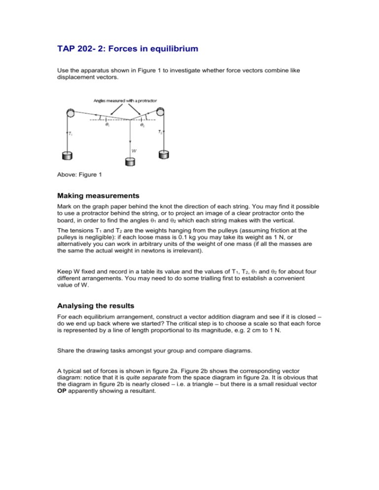
TAP 202- 2: Forces in equilibrium Use the apparatus shown in Figure 1 to investigate whether force vectors combine like displacement vectors. Above: Figure 1 Making measurements Mark on the graph paper behind the knot the direction of each string. You may find it possible to use a protractor behind the string, or to project an image of a clear protractor onto the board, in order to find the angles 1 and 2 which each string makes with the vertical. The tensions T1 and T2 are the weights hanging from the pulleys (assuming friction at the pulleys is negligible): if each loose mass is 0.1 kg you may take its weight as 1 N, or alternatively you can work in arbitrary units of the weight of one mass (if all the masses are the same the actual weight in newtons is irrelevant). Keep W fixed and record in a table its value and the values of T 1, T2, 1 and 2 for about four different arrangements. You may need to do some trialling first to establish a convenient value of W. Analysing the results For each equilibrium arrangement, construct a vector addition diagram and see if it is closed – do we end up back where we started? The critical step is to choose a scale so that each force is represented by a line of length proportional to its magnitude, e.g. 2 cm to 1 N. Share the drawing tasks amongst your group and compare diagrams. A typical set of forces is shown in figure 2a. Figure 2b shows the corresponding vector diagram: notice that it is quite separate from the space diagram in figure 2a. It is obvious that the diagram in figure 2b is nearly closed – i.e. a triangle – but there is a small residual vector OP apparently showing a resultant. Above: Figure 2 Can you see any assumption you are making in measuring the tensions which might tend to prevent the diagram from closing? What could you do to the apparatus which would have the effect of reducing the length OP? Practical advice A force board is not strictly necessary (clamped pulleys could be used) but even an improvised one out of peg board makes the whole arrangement much less likely to collapse in a cascade of slotted masses. The most convenient starting arrangement is the symmetrical 120° one, and then move away from that in controlled steps. In Figure 2(b) the residual vector OP can be attributed to experimental uncertainties in the measurements of angle, and regarded as some measure of the effect of friction at the pulleys. Technicians Note Apparatus force board with 2 pulleys (or equivalent robustly clamped arrangement) three 10 0.1 kg hanging masses* fine string graph paper protractor * If using a small board (30 30 cm), use 0.01 kg slotted masses. External references This activity is taken from Salters Horners Advanced Physics, AS, Section Higher, Faster, Stronger, HFS, Activity 1
