VECTOR ADDITION LAB PURPOSE: To experimentally verify the
VECTOR ADDITION LAB
PURPOSE:
To experimentally verify the rules for vector addition by graphical
(scale drawing) and by components.
APPARATUS:
Force Table with Pulleys
50g mass holders
Assortment of masses from 1g to 100g
METHOD:
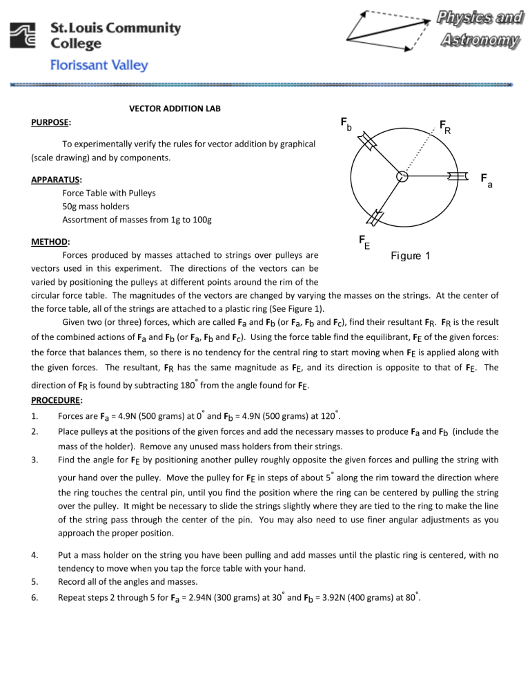
Forces produced by masses attached to strings over pulleys are vectors used in this experiment. The directions of the vectors can be varied by positioning the pulleys at different points around the rim of the circular force table. The magnitudes of the vectors are changed by varying the masses on the strings. At the center of the force table, all of the strings are attached to a plastic ring (See Figure 1).
Given two (or three) forces, which are called F a and F b (or F a, F b and F c), find their resultant F R. F R is the result of the combined actions of F a and F b (or F a, F b and F c). Using the force table find the equilibrant, F E of the given forces: the force that balances them, so there is no tendency for the central ring to start moving when F E is applied along with the given forces. The resultant, F R has the same magnitude as F E, and its direction is opposite to that of F E. The direction of F
R is found by subtracting 180° from the angle found for
F
E.
PROCEDURE:
1. Forces are F a = 4.9N (500 grams) at 0° and F b = 4.9N (500 grams) at 120°.
2. Place pulleys at the positions of the given forces and add the necessary masses to produce F a and F b (include the mass of the holder). Remove any unused mass holders from their strings.
3. Find the angle for F E by positioning another pulley roughly opposite the given forces and pulling the string with your hand over the pulley. Move the pulley for F
E in steps of about 5° along the rim toward the direction where the ring touches the central pin, until you find the position where the ring can be centered by pulling the string over the pulley. It might be necessary to slide the strings slightly where they are tied to the ring to make the line of the string pass through the center of the pin. You may also need to use finer angular adjustments as you approach the proper position.
4. Put a mass holder on the string you have been pulling and add masses until the plastic ring is centered, with no tendency to move when you tap the force table with your hand.
5. Record all of the angles and masses.
6. Repeat steps 2 through 5 for F a = 2.94N (300 grams) at 30° and F b = 3.92N (400 grams) at 80°.
7. Repeat steps 2 through 5 for F a = 1.96N (200 grams) at 0°, F b = 0.98N (100 grams) at 70° and F c = 0.98N (100 grams) at 160°.
Component Method
EXAMPLE
Now we will add the same three vectors above mathematically. Once again, they are: A =20m@45°, B =25m@300°, and
C =15m@210°
Find the x components:
A x
=A cos
A
=20m cos(45 )=14.1m
B x
=B cos
B
=25m cos(300 )=12.5m
C x
=C cos
C
=15m cos(210 )=-13.0m
R x
= A x+
B x+
C x
= 13.6m
Find the y components:
A
Y
=A sin
B
Y
=B sin
A
=20m sin(45 )=14.1m
B
=25m sin(300 )=-21.7m
C
Y
=C sin
C
=15m sin(210 )=-7.5m
R
Y
= A
Y+
B
Y+
C
Y
= -15.1m
Now that you have the components of the resultant vector, use the Pythagorean Theorem to find the magnitude of the resultant and the inverse tangent function to find the direction angle:
R = R
X
2
R
2
Y
( 13 .
6 m )
2
( 15 .
1 m )
2
=20.2m
R
= tan
1
R
Y
R
X tan
1
15
13 .
6
.
1 m m
=-48
-48 is the same as a positive 312 . So our resultant vector is R =20.2m@312 .
NAME_________________
DATE_________________
INSTRUCTOR_________________
ROSTER NUMBER_________________
VECTOR ADDITION LAB SHEET 1
DATA TABLE:
SETUP 1
SETUP 2
SETUP 3
CALCULATIONS:
F
A
F
B
F
C
F
E
SHOW ALL WORK (F
R
IS A VECTOR) ALSO PLACE ALL ANSWERS ON THE RESULTS TABLE
1.
Find the experimental value of F
R
for each of the three different setups.
2.
For all three setups find the experimental value of F
R
using the component method.
3.
Find F
R
for each setup using the graphical method (Make a scaled drawing). Choose a scale that the drawing fills half a page. Label all magnitudes and angles on the drawings and list the scale used. Use the graph paper provided.
4.
Calculate the percent errors ( using magnitudes only ) of the experimental results to the component method results and the graphical method to the component method.
RESULTS TABLE:
SETUP 1
SETUP 2
SETUP 3
Experimental
F
R
Graphical
F
R
Component
F
R
Percent Error
Experimental
Percent Error
Graphical
CONCLUSION:
VECTOR ADDITION LAB SHEET 2
TURN IN:
VECTOR ADDITION LAB SHEET 1 AND 2, 3 GRAPHS
