ZLA - Pharos University in Alexandria
advertisement
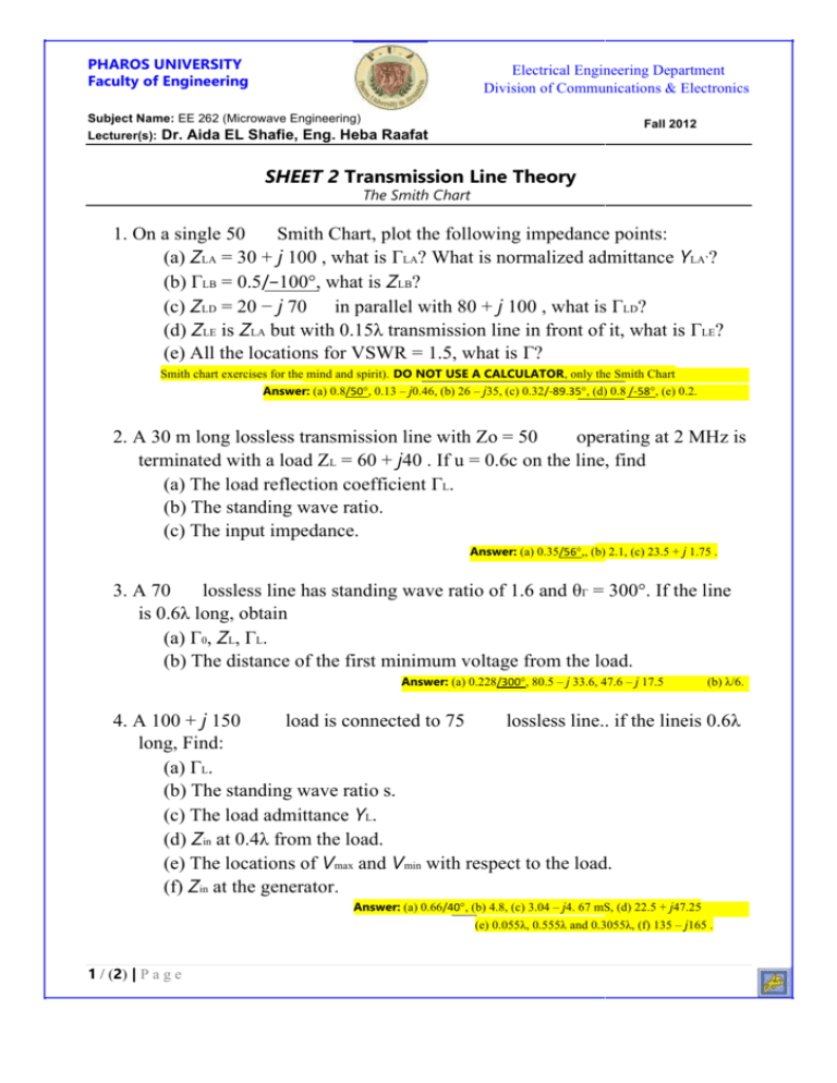
PHAROS UNIVERSITY Faculty of Engineering Electrical Engineering Department Division of Communications & Electronics Subject Name: EE 262 (Microwave Engineering) Lecturer(s): Dr. Aida EL Shafie, Eng. Heba Fall 2012 Raafat SHEET 2 Transmission Line Theory The Smith Chart 1. On a single 50 Smith Chart, plot the following impedance points: (a) ZLA = 30 + j 100 , what is ГLA? What is normalized admittance YLA’? (b) ГLB = 0.5/−100°, what is ZLB? (c) ZLD = 20 − j 70 in parallel with 80 + j 100 , what is ГLD? (d) ZLE is ZLA but with 0.15λ transmission line in front of it, what is ГLE? (e) All the locations for VSWR = 1.5, what is Г? Smith chart exercises for the mind and spirit). DO NOT USE A CALCULATOR, only the Smith Chart Answer: (a) 0.8/50°, 0.13 – j0.46, (b) 26 – j35, (c) 0.32/-89.35°, (d) 0.8 /-58°, (e) 0.2. 2. A 30 m long lossless transmission line with Zo = 50 operating at 2 MHz is terminated with a load ZL = 60 + j40 . If u = 0.6c on the line, find (a) The load reflection coefficient ГL. (b) The standing wave ratio. (c) The input impedance. Answer: (a) 0.35/56°,, (b) 2.1, (c) 23.5 + j 1.75 . lossless line has standing wave ratio of 1.6 and θГ = 300°. If the line 3. A 70 is 0.6λ long, obtain (a) Г0, ZL, ГL. (b) The distance of the first minimum voltage from the load. Answer: (a) 0.228/300°, 80.5 – j 33.6, 47.6 – j 17.5 (b) λ/6. 4. A 100 + j 150 load is connected to 75 lossless line.. if the lineis 0.6λ long, Find: (a) ГL. (b) The standing wave ratio s. (c) The load admittance YL. (d) Zin at 0.4λ from the load. (e) The locations of Vmax and Vmin with respect to the load. (f) Zin at the generator. Answer: (a) 0.66/40°, (b) 4.8, (c) 3.04 – j4. 67 mS, (d) 22.5 + j47.25 (e) 0.055λ, 0.555λ and 0.3055λ, (f) 135 – j165 . 1 / (2) | P a g e PHAROS UNIVERSITY Faculty of Engineering Subject Name: EE 262 (Microwave Engineering) Lecturer(s): Dr. Aida EL Shafie, Eng. Heba Electrical Engineering Department Division of Communications & Electronics Fall 2010 Raafat 5. On a single 50 Smith Chart, find and plot the following impedances and find their values in normalized values and in Ohms. Also, find the reflection coefficients at every plane. All non-labeled t-lines have zero electrical length. Hope you the best Dr. Aida EL Shafie Eng. Heba Raafat 2 / (2) | P a g e


