EM-2-report
advertisement
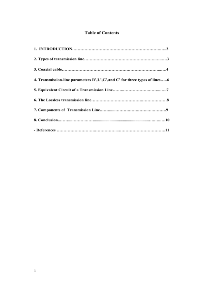
Table of Contents 1. INTRODUCTION……………………………………………………….…..2 2. Types of transmission line…………………………………………….…..….3 3. Coaxial cable………………………………………….…………………...….4 4. Transmission-line parameters R’,L’,G’,and C’ for three types of lines…..6 5. Equivalent Circuit of a Transmission Line……..……………….……...…..7 6. The Lossless transmission line……………………………….………………8 7. Components of Transmission Line.……......……….…….…….….……….9 8. Conclusion..……....……….…….....................................................….…..….10 - References ……………………….……………...…………………………….11 1 Introduction Transmission lines are commonly used in power distribution (at low frequencies) and in communications (at high frequencies) to transfer energy from one point to another (from a source to a load). Various kinds of transmission lines such as the twisted-pair and coaxial cables (thinnet and thicknet) are used in computer networks such as the Ethernet and internet. A transmission line basically consists of two or more parallel conductors used to connect a source to a load. The source may be a hydroelectric generator, a transmitter, or an oscillator; the load may be a factory, an antenna, or an oscilloscope, respectively. Typical transmission lines include coaxial cable, a two-wire line, a parallel-plate. Transmission line problems are usually solved using EM field theory and electric circuit theory, the two major theories on which electrical engineering is based. In this report, we use circuit theory because it is easier to deal with mathematically. The basic concepts of wave propagation. AC resistance of a conductor is always higher than its DC resistance due to the skin effect forcing more current flow near the outer surface of the conductor. The higher the frequency of current, the more noticeable skin effect would be. 2 2. Types of transmission line According to their propagation modes, The transmission lines may be classified into two basic types are : 2.1 Transverse electromagnetic (TEM) transmission lines The case of this call (TEM mode) because in this transmission lines the Waves propagation along these lines are characterized by electric and magnetic fields that are entirely transverse to the direction of propagation (i.e. They have no electric-or-magnetic field components along its direction of propagation). Figure.1 show different TEM structures , a good example for TEM mode is coaxial cable which is shown in the (fig1-a) it's consist of two conducting cylindrical plane inner and outer and dielectric material between them and as we see in the (fig1-a) the direction of energy flow is along the length of the coaxial cable. The other examples are a two- wire line (fig1-b) which consists of two parallel rods, a parallel – plate line as shown in (fig1-c), an unbalanced line (fig1-d) that his structure is very simple with one wire connected with +ve terminal of voltage source and the –ve terminal connected to the ground and (fig1-e) show a micro strip line which consist of two strip the upper is smallest on width than the lower and there are dielectric slab between them where the direction of energy flow is along the strip. ▪ ▪ All of these transmission lines can transfer energy with high efficiency. A common feature among TEM lines is that they consist of two parallel conducting surfaces. a b c d e Figure 1 3 2.2 -Higher-order transmission lines: Waves propagating along these lines have at least one significant field component in the direction of propagation. Hollow conducting waveguides, dielectric rods, and optical fibers belong to this class of lines. 3. Co-axial Cable: Coaxial cable is called "coaxial" because it includes one physical channel that carries the signal surrounded (after a layer of insulation) by another concentric physical channel, both running along the same axis. The outer channel serves as a ground. Many of these cables or pairs of coaxial tubes can be placed in a single outer sheathing and, with repeaters, can carry information for a great distance. Coaxial cable is the kind of copper cable used by cable TV companies between the antenna and user homes and businesses. Coaxial cable is sometimes used by telephone companies from their central office to the telephone poles near users. (a) coaxial cable (b) Twisted-pair cable figure 2 The Coaxial cable carries signals of higher frequency ranges (higher Bandwidth) than twisted pair. The coaxial cable consists two conductors, Inner conductor carries signal and outer one serves as shield against noise and as the second conductor, which completes the circuit. Instead of having two wires as twisted-pair calbe(fig2-b), coax has a central core conductor of solid or stranded wire (usually copper) enclosed in an insulating sheath, which is in turn, encased in an outer conductor of metal foil, braid, or a combination of the two. The outer metallic wrapping serves both as a shield against noise and as the second conductor, which completes the circuit, This outer conductor is also enclosed in an insulating sheath, and the whole cable is protected by a plastic cover(PVC). figure.3 We used a connector with coaxial cable , its called a BNC connector(short for British Naval Connector) is mounted at each end of a cable(as shown in fig.3). 4 General Rules for Coax: 3 Attenuation or Loss Raising the D/d ratio lowers attenuation 5 Transmission-Line Input Impedance The input impedance at a distance l from the load is: When the load is a short circuit, Zi = jZo tan (l). When the load is an open circuit, Zi = -jZo cot (l) 4. Transmission-line parameters R’,L’,G’,and C’ for three types of lines 6 5. An Equivalent Circuit of a Transmission Line. Characteristics of a T.L. (uniformly distributed) are determined by: Electrical proprieties: wire conductivity and insulator dielectric Physical properties: wire diameter and conductor spacing Primary electric constants: Series DC resistance R & Inductance L Shunt Capacitance C & Conductance G Circuit Model: 7 z 6. The Lossless transmission line. 6.1 The Losses transmission line. 6.1.1 Conductor losses : It is because current flows through a transmission line and a line has a finite resistance there is an un-avoidable power loss. This is sometimes called conductor loss or conductor heating loss and is simply a power loss. To reduce conductor loss simply shorten the transmission line or use a larger diameter wire. Conductor loss depends somewhat on frequency because of a phenomenon called the skin effect. 6.1.2 Dielectric heating losses: 8 A difference of potential between two conductors of a metallic transmission line causes dielectric heating. Heat is form of energy and must be taken from the energy propagating down the line. For air dielectric transmission lines the heating is negligible. For solid core transmission lines dielectric heating loss increases with frequency. 7. Components of Transmission Line 1- Conductor 2- Earth wire 3-Insulator 4- Transmission Tower 5- Wave trap and other hardware (Clamp, Spacer, Vibration dampers, connectors etc.) ***The figure below shown the component of transmission line 9 8. Conclusion The transmission line is the important structure to establish any system. fig. shows the system elements (a source, a transmission line and a load) 10 References - Ulaby,Fawwaz T.(Fawwaz Tayssir),Fundamentals of applied electromagnetic /Fawwaz T. Ulaby. - http://searchnetworking.techtarget.com/definition/coaxial-cable-illustrated - http://sparc.nfu.edu.tw/~lyc/intro_net/ch07.pdf - www.qec.edu.sa 11

