Lesson 26 (1) LC Circuit The circuit shown can be used to first
advertisement

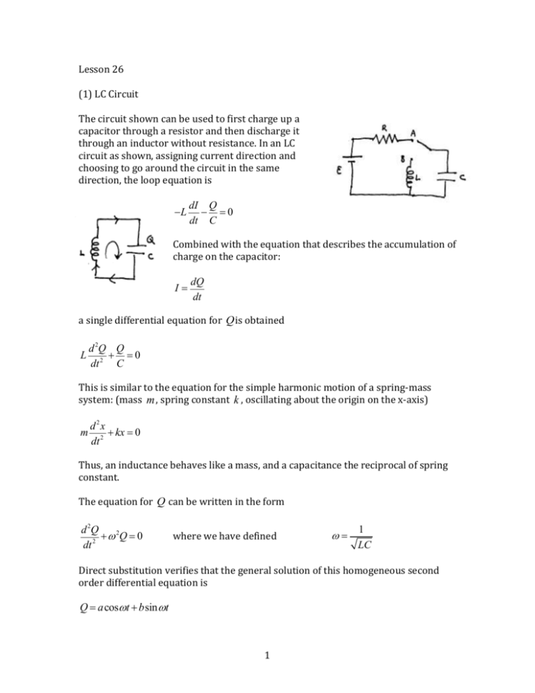
Lesson 26 (1) LC Circuit The circuit shown can be used to first charge up a capacitor through a resistor and then discharge it through an inductor without resistance. In an LC circuit as shown, assigning current direction and choosing to go around the circuit in the same direction, the loop equation is -L dI Q - =0 dt C Combined with the equation that describes the accumulation of charge on the capacitor: I= dQ dt a single differential equation for Q is obtained L d 2Q Q + =0 dt 2 C This is similar to the equation for the simple harmonic motion of a spring-mass system: (mass m , spring constant k , oscillating about the origin on the x-axis) m d2x + kx = 0 dt 2 Thus, an inductance behaves like a mass, and a capacitance the reciprocal of spring constant. The equation for Q can be written in the form d 2Q + w 2Q = 0 2 dt where we have defined w= 1 LC Direct substitution verifies that the general solution of this homogeneous second order differential equation is Q = acoswt + bsin wt 1 where a and b are arbitrary constants . The current is found by differentiation: I= dQ = -w asin wt + w bcoswt dt The charge on the capacitor and the current oscillate with period T= 2p w f= and frequency w 2p The arbitrary constants are determined from initial conditions. If the capacitor is charged up to Q0 and there is no current in the inductor initially, we find a = Q0 b = 0 . The solution is Q = Q0 coswt I = -wQ0 sinwt (2) Energy Conservation Using the above solutions, we can calculate the total energy ö Q 1 1 Q2 1 2 æ 2 2 1 U = U L +UC = LI 2 + = Q0 ç Lw sin wt + cos2 wt ÷ = 0 ø 2C 2 2 C 2 è C showing that it is conserved, and equal to the initial energy stored in the capacitor. In the general case, conservation of energy can be derived by multiplying the circuit equation by I , finding -LI dI Q - I =0 dt C which can be transformed to -LI dI Q dQ =0 dt C dt d æ 1 2 1 Q2 ö ç LI + ÷=0 dt è 2 2 Cø and then to The stored energy in the circuit swaps back and forth between the inductor and the capacitor. (3) Phasers The general solution Q = acoswt + bsin wt can be written in the form 2 Q = Acos (wt + a ) where A = a 2 + b2 and the angle a is defined by cosa = a a +b 2 2 sin a = - b a + b2 2 The angle a can be restricted to the range -p £ a £ p as a change of 2p does not alter the value of a trigonometric function. The proof follows from the trigonometric identity cosq1 cosq2 -sinq1 sinq2 = cos(q1 + q2 ) with q1 = wt q2 = a For example, it can be shown that sin wt = cos (wt - p 2) - coswt = cos (wt + p ) -sin wt = cos (wt + p 2) The quantity Acos (wt + a ) , where A is known as the amplitude and wt + a the phase, can be pictured as the x-component of a vector Q on the x-y plane known as the phaser as shown. The phaser rotates with angular velocity w in the counter-clockwise direction. Two phasers with the same frequency maintain the same phase difference at all times. The one with the larger phase is said to lead the other, while the one with the lesser phase is said to lag the other. Thus, for example, sin wt lags coswt by 90 -sin wt leads coswt by 90 The graph below shows that the same phase occurs later for sin wt than for coswt . 3 (4) RLC Circuit In an RLC circuit without any source of emf, the loop equation is -L dI Q - IR - = 0 dt C From this we can be derive d æ 1 2 1 Q2 ö 2 ç LI + ÷ = -I R < 0 dt è 2 2 Cø The energy stored in the circuit therefore continues to decrease to zero. The loop equation also leads to the following equation for the charge Q : d 2Q dQ Q L 2 +R + =0 dt dt C To solve it, we first rewrite it as d 2Q 1 dQ + + w 02Q = 0 2 dt t dt where t = L 1 w0 = R LC and look for solution in the form Q = Aeg t . Substitution into the equation yields the following equation for g : 1 g 2 + g + w 02 = 0 t 4 The solutions are æ1 ö 1 g1 = - - ç ÷ - w 02 è 2t ø 2t 2 provided æ1 ö 1 g 2 = - + ç ÷ - w02 è 2t ø 2t 2 L 1 ³ w 0 or R ³ 2 C 2t When g1 ¹ g 2 , we find the general solution Q = aeg1t + beg 2t which decays to zero exponentially. The circuit is said to be overdamped. At low enough resistance, when the form Q = Aeg t cosw1t 1 < w 0 , g 1 and g 2 do not exist. We try a solution in 2t so that dQ = A (g eg t cosw1t - w1eg t sin w1t ) dt d 2Q = A (g 2 eg t cosw1t - gw1eg t sin w1t - gw1eg t sin w1t - w12eg t cosw1t ) = A éë(g 2 - w12 ) eg t cosw1t - 2gw1eg t sin w1t ùû 2 dt Substituting into the differential equation for Q and equating the coefficients of the terms eg t cosw1t and eg t sin w1t to zero: 1 1 - 2gw1 - w1 = 0 g 2 - w12 + g + w02 = 0 t t The solutions are 1 g =2t æ 1 ö w1 = w - ç ÷ è 2t ø 2 2 0 The charge undergoes oscillations with frequency w1 2p as it decays. The circuit is said to be underdamped. It can be similarly shown that Q = Aeg t sin w1t is also a solution so that the general solution is Q = eg t (acosw1t + bsin w1t) . 5 1 is known as critically damped. In this case, g1 = g 2 and we have 2t found only one solution aeg t . It can be shown that in this case teg t is another solution, so that the general solution is Q = eg t ( a + bt ) The case w 0 = (5) Driven RLC Circuit For an RLC circuit with a source of AC emf ℇ = ℇ0 𝑐𝑜𝑠𝜔𝑡, the circuit equation is the inhomogeneous equation 𝑑2𝑄 𝑑𝑄 𝑄 𝐿 2 +𝑅 + = ℇ0 𝑐𝑜𝑠𝜔𝑡 𝑑𝑡 𝑑𝑡 𝐶 A particular solution can be sought in the form Q = acoswt + bsin wt Substituting this and dQ = -w asin wt + w bcoswt dt d 2Q = -w 2 acoswt - w 2 bsin wt 2 dt into the equation and equating the coefficients of the coswt and sin wt terms, we find 1 (−𝜔2 𝐿 + ) 𝑎 + 𝜔𝑅𝑏 = ℇ0 𝐶 1 −𝜔𝑅𝑎 + (−𝜔2 𝐿 + ) 𝑏 = 0 𝐶 which can be solved for a, b , resulting in 1 (−𝜔2 𝐿 + 𝐶 ) 𝜔𝑅 𝑄 = ℇ0 [ 𝑠𝑖𝑛𝜔𝑡] 2 𝑐𝑜𝑠𝜔𝑡 + 1 1 2 2 2 2 2 2 2 𝜔 𝑅 + (−𝜔 𝐿 + 𝐶 ) 𝜔 𝑅 + (−𝜔 𝐿 + 𝐶 ) The current is obtained from the time derivative of Q , and can be written in the form 𝐼 = 𝐼0 𝑐𝑜𝑠(𝜔𝑡 + 𝛼) 6 𝐼0 = 𝑐𝑜𝑠𝛼 = ℇ0 2 √𝑅 2 + ( 1 − 𝜔𝐿) 𝜔𝐶 1 − 𝜔𝐿 𝜔𝐶 𝑠𝑖𝑛𝛼 = 2 √𝑅 2 + ( 1 − 𝜔𝐿) 𝜔𝐶 𝑅 2 √𝑅 2 + ( 1 − 𝜔𝐿) 𝜔𝐶 The general solution is the sum of the particular solution and the general solution of the homogeneous equation. The latter decays to zero after approximately an L/R time. The particular solution persists, and can be considered to be the steady state solution. We will find another derivation of the steady state solution in the lessons to follow. 7 8
![Sample_hold[1]](http://s2.studylib.net/store/data/005360237_1-66a09447be9ffd6ace4f3f67c2fef5c7-300x300.png)


