Fig… Type of Single Mode Fiber - grupo3
advertisement

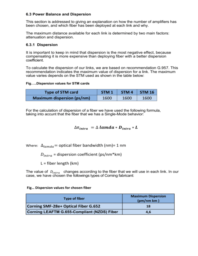
6.3 Power Balance and Dispersion This section is addressed to giving an explanation on how the number of amplifiers has been chosen, and which fiber has been deployed at each link and why. The maximum distance available for each link is determined by two main factors: attenuation and dispersion. 6.3.1 Dispersion It is important to keep in mind that dispersion is the most negative effect, because compensating it is more expensive than deploying fiber with a better dispersion coefficient. To calculate the dispersion of our links, we are based on recommendation G.957. This recommendation indicates the maximum value of dispersion for a link. The maximum value varies depends on the STM used as shown in the table below: Fig…..Dispersion values for STM cards Type of STM card Maximum dispersion (ps/nm) STM 1 1600 STM 4 1600 STM 16 1600 For the calculation of dispersion of a fiber we have used the following formula, taking into accunt that the fiber that we has a Single-Mode behavior: ∆𝝉𝒊𝒏𝒕𝒓𝒂 = ∆ 𝒍𝒂𝒎𝒅𝒂 ∗ 𝑫𝒊𝒏𝒕𝒓𝒂 ∗ 𝑳 Where: ∆𝑙𝑎𝑚𝑑𝑎 = optical fiber bandwidth (nm)= 1 nm 𝐷𝑖𝑛𝑡𝑟𝑎 = dispersion coefficient (ps/nm*km) L = fiber length (km) The value of 𝐷𝑖𝑛𝑡𝑟𝑎 changes according to the fiber that we will use in each link. In our case, we have chosen the followings types of Corning fabricant: Fig… Dispersion values for chosen fiber Type of fiber Maximum Dispersion (pm/nm km ) Corning SMF-28e+ Optical Fiber G.652 18 Corning LEAFTM G.655-Compliant (NZDS) Fiber 4,6 According with this we obtained the maximal distance allowed to transmit over the link, without dispersion. Maximal distance (Corning SMF-28e+ Optical Fiber G.652) = 88 km Maximal distance (Corning LEAFTM G.655-Compliant (NZDS) Fiber) = 347 km 6.3.2 Technical characteristics of the equipment All along a transmission link, characteristics of the equipment influence the power balance of the link. In this part of the project we will analyze the attenuation introduced by the equipment’s used in our network. Losses in signal quality are modeled by: optical fiber losses, connectors, splices and losses due to multiplexers and de-multiplexers. The general equation for obtaining the total link losses is: 𝑨(𝒅𝑩) = 𝜶 ∗ 𝑳 + 𝜶𝒔 ∗ 𝒙 + 𝜶𝒄 ∗ 𝒚 Where: 𝛼 is the attenuation factor through the distance [dB/km]; L is the link distance in km 𝛼𝑠 is the mean splice loss (dB) x is the total number of splices for any given link 𝛼𝑐 is the mean loss due to the STM connectors, mux/de mux connectors, amplifiers connectors y is the total number of connectors 6.3.3 Fibers Optical fiber typically consists of a transparent core surrounded by a transparent cladding material with a lower index of refraction. Light is kept in the core by total internal reflection. This causes the fiber to act as a waveguide. Fibers which support many propagation paths or transverse modes are called multi-mode fibers (MMF), while those which can only support a single mode are called single-mode fibers (SMF). The single mode optical fibers have a diameter of the nucleus smaller than multimode fibers, allowing a single way forward is (propagation mode and not oscillation mode) and prevent the multimodal dispersion. Single mode fibers are also characterized by a lower attenuation than multimode fiber, but the coupling of light becomes more complicated and the tolerances of connectors and splices are stricter. In contrast to the multimode fibers, single mode fibers allow to be up to great distances and transmit higher bit rates, which are mainly limited by the chromatic dispersion and non-linear effects. For all these reasons we have chosen to use single mode fibers in onCAT network. Fig… Type of Single Mode Fiber Type of fiber Maximum Att. Dispersion (pm/nm (dB/km) km ) No Channels Att. Fusion Fibers (dB/ 5km) Corning SMF-28e+ Optical Fiber G.652 0,2 18 16 0,02 Corning LEAFTM G.655Compliant (NZDS) Fiber 0,25 4,6 80 0,02 System fiber-mux/de-mux in coupled by connectors. Each system fiber + mux/demux is composed by 6 connectors. Fig…Connectors loss Att Connectors (dB) 0,2 Losses associated to the connecters are known as Insertion Losses and they are usually lower than 1 dB. Those losses define the power loss when coupling the fiber ends or in other words, the power loss due to coupling mismatch and small differences in reflection index. 6.3.4 Optical Amplifier An optical amplifier is used in long fiber links to make useful the low power received signal. This device decoder the received data, regenerates the digital pulses and overwrites the regenerator section of the frame (RSOH). Finally, sends it again over the path to the next node. Fig …Type of amplifier EDFA OA 4500 Amplifiers Series Total input signal power Total ouput signal power Signal Gain -30 to 2 dBm 21,5 dBm 19 to 32 dBm Fig…Gain performance of EDFA OA 4500 Amplifiers Series Gain Maximum output power = 21,5 dBm 32 dB 19 dB Sensitivity -30 dBm -10,5 dBm Pr max 2 dBm Power received Fig…Power performance of EDFA OA 4500 Amplifiers Series Output power 21,5 dBm 2 dBm Sensitivity -30 dBm -10,5 dBm Pr max 2 dBm Power received Fig…. STM cards characteristics Type of STM card Transmited Power (dBm) Sensitivity (dBm) Maximum dispersion (ps/nm) Source linewidth (nm) (SM laser) STM 1 -5 -34 1600 STM 4 -3 -28 1600 STM 16 -2 -27 1600 1 1 1 We will work with STM 16 characteristics , because this card is more restrictive. We use for transmitted power Tx= -2 dBm and for sensitivity Rx= -27 dBm. Total Attenuation We make the attenuation calculation using the following formula: 𝒅𝑩 𝜶𝒕𝒐𝒕𝒂𝒍 = 𝜶𝒇𝒊𝒃𝒆𝒓 ( ) ∗ 𝑳 (𝒌𝒎) + 𝜶𝒄𝒐𝒏𝒏𝒆𝒄𝒕𝒐𝒓𝒔 ∗ 𝟒 + 𝜶𝒑𝒐𝒓 𝒔𝒍𝒊𝒄𝒆 ∗ 𝒌𝒎 𝒐 𝒏 𝒔𝒍𝒊𝒄𝒆𝒔 + 𝜶𝒎𝒖𝒙 ∗ 𝟐(𝒎𝒖𝒙 𝑻𝒙 𝒂𝒏𝒅 𝒅𝒆𝒎𝒖𝒙 𝑹𝒙) In order to fix the maximal distance Lmax that allows us to transmit a signal without using amplifiers we will use the following formula: 𝜶𝒎𝒂𝒙 = [(𝑹𝒙 − 𝑻𝒙) + 𝜶𝑻𝒐𝒕𝒂𝒍 ]/[𝜶𝑭𝒊𝒃𝒆𝒓 + ( 𝜶𝒔𝒍𝒊𝒄𝒆𝒔 /𝟓)] Considering the characteristics of optical multiplexers and demultiplexers presented in the chapter number 6.2.1, we make the calculation of Lmax considering next cases: WDM technology CWDM 1 channels CWDM 2 channels CWDM 8 channels DWDM 8 channels DWDM 13 channels DWDM 40 channels Att Mux/Demux 0 (No use mux) 4,6 7,4 8 7 12 L max 120,59 94,12 80,4 62,20 66,14 46,46 After we obtain the maximal distance Lmax that allows us to transmit the signal without using amplifiers, we look to links that are bigger than Lmax. In order to have a proper transmission, for this links we use amplifiers. For links with one amplifier we calculate the new maximal distance, Lmax, at which the amplifier can transmit the signal. There can be situations in which the amplifier is not able to cover all the link distance, when transmitting the signal. For this case we will use the same formula when we make the new Lmax calculation, but we will use the transmitted power from datasheet of the amplifier and the sensibility from datasheet of the demultiplexer. For the value of new Lmax we obtain the links that needs 2 amplifiers. When we calculate the Lmax for links that need more than one amplifier we have to calculate also the maximal distance between 2 amplifiers. For this distance we use the input power 2 dBm, representing the addition between the signal gain of the amplifier and the sensibility of the amplifier. For links that are using 2 Fibers SP-Ring Protection, we take in count also the traffic for the protection. That means we have double number of STM cards representing protection and working traffic. For the value of new Lmax, representing the maximal distance at which we can transmit a signal using an amplifier and adding the maximal distance at which the signal can be transmitted without using an amplifier, we obtain the number of AO that we need in each link. In our case we have links for which we don’t use amplifiers and links in which we needs one or two amplifiers. Fig…. Link with one amplifier ADM/DXC Mux AO Demux ADM/DXC Fig … Lmax calculate for links with one or more amplifiers Link description No. Channels Pt Sensibility Lmax Lmax from STM to AO Lmax from AO to STM Lmax from AO to AO Lmax from STM to AO Lmax from AO to STM Lmax from AO to AO DWDM 13 channels -2 -30 93,31 DWDM 13 channels 2 -27 97,25 DWDM 13 channels 2 -30 109,06 DWDM 8 channels -2 -30 91,34 DWDM 8 channels 2 -27 91,34 DWDM 8 channels 2 -30 99,21 Fig… Link with 2 amplifier AO ADM/DXC Mux AO Demux ADM/DXC Fig… Lmax calculated for links with one amplifier and 2 amplifiers Real No. Lmax # AOs L max with 1 AO Link Distance channels WDM technology without AO used or 2 AO 1 182,68 Igualada-Manresa 78,8 6 DWDM 8 channels 62,2 1 182,68 Tarragones – Montsia 74 6 DWDM 8 channels 62,2 1 190,55 Lerida - Tarragona 104 13 DWDM 13 channels 66,14 1 190,55 Lerida - Tarragona 2 97,9 13 DWDM 13 channels 66,14 2 299,6 Lerida - Manresa- Gerona 223 13 DWDM 13 channels 66,14 2 299,6 Lerida - Monjo- Gerona 254 13 DWDM 13 channels 66,14 1 190,55 Tarragona - Barcelona 97,4 13 DWDM 13 channels 66,14 1 190,55 Tarragona - Barcelona 2 87 13 DWDM 13 channels 66,14 1 190,55 Barcelona - Blanes-Gerona 119,9 13 DWDM 13 channels 66,14 1 190,55 Barcelona - Gerona 102 13 DWDM 13 channels 66,14 In this section of the project we assure the proper signal transmission in all our network. Using optical amplifiers we get sure that signal transmission over the fiber has the needed power to travel all along the network.


