Photometric law of distance
with Cobra4
TEP
Related topics
Luminous flux, quantity of light, luminous intensity, illuminance, luminance.
Principle
The luminous intensity emitted by a punctual source is determined as a function of distance.
Material
1
2
1
1
1
1
3
1
2
1
1
1
1
1
1
1
1
1
1
Cobra4 Wireless Manager
Cobra4 Wireless-Link
Cobra4 Sensor-Unit Energy
Cobra4 Sensor-Unit Motion, ultrasound motion detector
Holder for Cobra4 with support rod
Power supply, 0…12 V DC/ 6 V, 12 V AC, 230 Volt
Stand tube
Distributor
Barrel base PHYWE
Meter scale, l = 1000 mm
Bench clamp PHYWE
PEK photodiode, G1
Incandescent lamp, 6 V/5 A, E 14
Lamp holder E 14, on stem
Connecting cord, 32 A, l = 75 cm, red
Connecting cord, 32 A, l = 75 cm, blue
Right angle clamp PHYWE
Screen, metal, 300×300 mm
Software Cobra4 - multi-user licence
12600-00
12601-00
12656-00
12649-00
12680-00
13505-93
02060-00
06024-00
02006-55
03001-00
02010-00
39119-01
06158-00
06175-00
07362-01
07362-04
02040-55
08062-00
14550-61
Additionally required
1 PC with USB-interface, Windows XP or higher
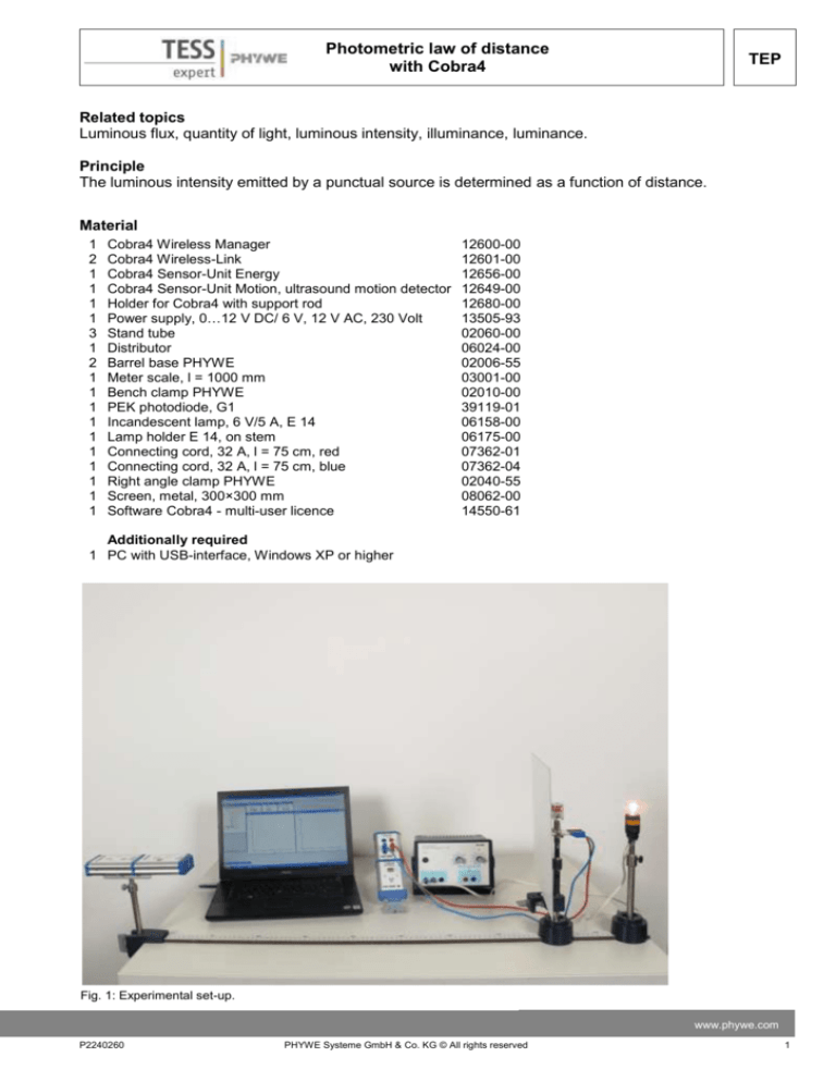
Fig. 1: Experimental set-up.
www.phywe.com
P2240260
PHYWE Systeme GmbH & Co. KG © All rights reserved
1
TEP
Photometric law of distance
with Cobra4
Tasks
1. The luminous intensity emitted by a punctual source is determined as a function of distance from the
source.
2. The photometric law of distance is verified by plotting illuminance as a function of the reciprocal value
of the square of the distance.
Experimental objective
The luminous intensity is a function of the distance of the light sensor from the light source. The law for
point light sources on which this is based should be determined.
Set-up and procedure
The experimental set-up is shown in Fig. 1. Align the filament of the lamp such that its wide side faces
the photocell. Adjust the photodiode in such a manner that it remains oriented towards the lamp’s filament when moved. Naturally, the lamp’s filament and the photocell must be mounted at the same height
above the table. Since the distance law which is to be verified is only valid for point light sources, an initial separation (sensor – lamp filament) of 15 cm should be used. Darken the room or shield the experiment from direct sunlight. Connect the Cobra4 Wireless Manager to the USB interface of the computer,
plug the Cobra4 Sensor-Unit Energy on the first Cobra4 Wireless-Link, the Cobra4 Sensor-Unit Motion to
the second Cobra4 Wireless-Link and fix this combination with the holder to the bench clamp.
Load the “Photometric law of distance” experiment. (Experiment > Open experiment). All pre-settings
that are necessary for measured value recording are now carried out. To measure the path with the motion sensor put the photocell in the initial position (15 cm away from lamp
filament). Start the measurement ( ) and move slowly (about 0.5 cm/s)
the photocell along the meter scale away from lamp filament. At a distance of approximately 70 cm you can terminate the measurement ( ),
as the luminous intensity has now become very low and in addition the
diffuse light fraction is relatively large, and send the results to measure Fig. 2: Saving measurements.
(Fig. 2)
Theory and evaluation
A punctual light source of luminous intensity I (Candela/cd) emits a light flux Φ (Lumen/lm) throughout a
solid angle ω. Luminous intensity in a solid angle element dω amounts to equation 1:
𝐼=
𝑑𝛷
[𝑐𝑑]
𝑑𝜔
(1)
For luminous sources extended in space (also such which emit no light by themselves, but which are reflecting), luminance B is given by equation 2:
𝐵=
𝑑𝐼 𝑐𝑑
[
]
𝑑𝑎 𝑐𝑚2
(2)
If an area dA* is illuminated by a luminous flux dΦ, illuminance E (Lux/lx) is given by equation 3:
𝐸=
2
𝑑𝛷
[𝑙𝑥]
𝑑𝐴∗
PHYWE Systeme GmbH & Co. KG © All rights reserved
(3)
P2240260
Photometric law of distance
with Cobra4
Fig. 3 gives a schematic representation of the
illumination of a surface element dA* through a
punctual light source P. The luminous intensity
of the source is I and its distance from the surface element is r, the perpendicular to the surface element points in the direction of the connecting line with the light source. The illuminance E is given by equation 4:
𝐸=
TEP
Fig. 3: Schematic determination of the photometric law of distance.
𝑑𝛷
𝑑𝛷/𝑑𝜔
=
∗
𝑑𝐴
𝑑𝜔 /𝑑𝐴∗
(4)
With dω = dA* / r² and (1) one obtains equation 5:
𝐸=
𝐼
𝑟2
(5)
Equation (5) describes the photometric law of distance. According to this, the illuminance E of a surface
decreases proportionally to the square of distance r for constant luminous intensity I.
Analysis of the measurement
For the analysis of the results the measured distance between screen and motion sensor is converted into the actual distance lamp/diode with aid of the calculated channel.
The luminous intensity is plotted as a function of actual distance between the lamp filament and sensor
(see Fig. 4).
Fig. 4:
Luminous intensity as a function of distance (Lamp – Diode).
www.phywe.com
P2240260
PHYWE Systeme GmbH & Co. KG © All rights reserved
3
Photometric law of distance
with Cobra4
TEP
After conversion use the same Analysis / Channel modification window for the calculation of the square
of the inverse value 1/(s*s) (see Fig. 5):
Fig. 5:
Parameters of the channel modification.
In Fig. 6 the measured values of the luminous intensity are plotted as a function of the reciprocal values
of the square of distance r. The photometric law of distance is verified by the linearity of the primary
graph.
Fig. 6:
4
Luminous intensity as a function of the square of the reciprocal of the distance
(lamp – diode).
PHYWE Systeme GmbH & Co. KG © All rights reserved
P2240260

