CHAPTER 9. PHOTOMETRY AND RADIOMETRY Photometry is the
advertisement
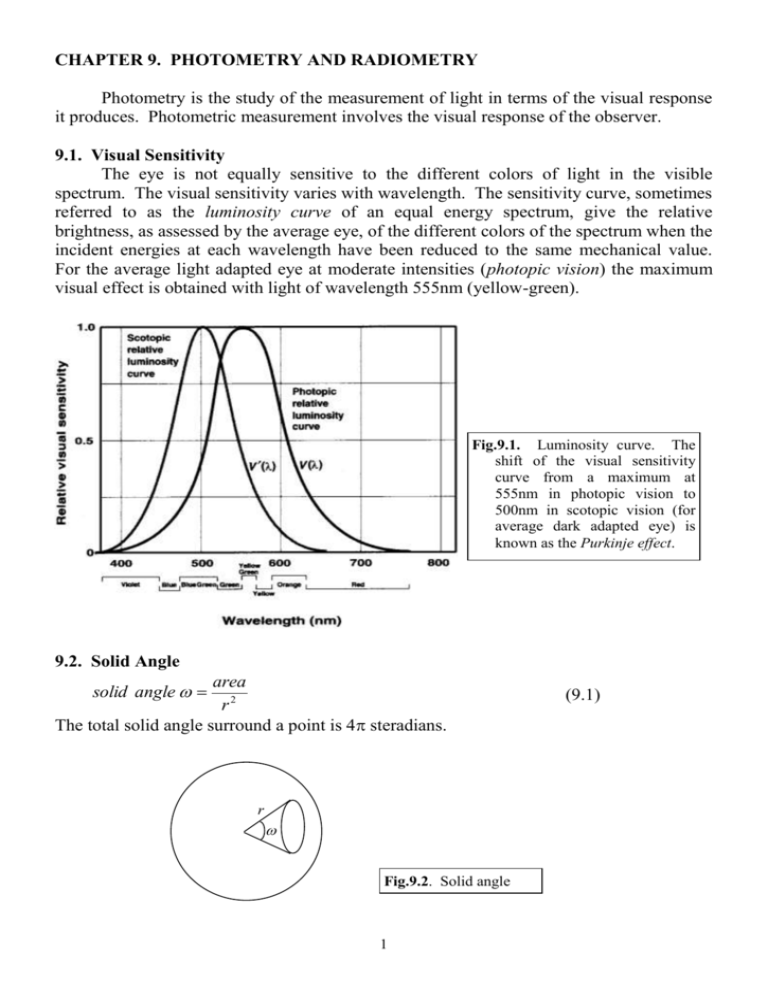
CHAPTER 9. PHOTOMETRY AND RADIOMETRY Photometry is the study of the measurement of light in terms of the visual response it produces. Photometric measurement involves the visual response of the observer. 9.1. Visual Sensitivity The eye is not equally sensitive to the different colors of light in the visible spectrum. The visual sensitivity varies with wavelength. The sensitivity curve, sometimes referred to as the luminosity curve of an equal energy spectrum, give the relative brightness, as assessed by the average eye, of the different colors of the spectrum when the incident energies at each wavelength have been reduced to the same mechanical value. For the average light adapted eye at moderate intensities (photopic vision) the maximum visual effect is obtained with light of wavelength 555nm (yellow-green). Fig.9.1. Luminosity curve. The shift of the visual sensitivity curve from a maximum at 555nm in photopic vision to 500nm in scotopic vision (for average dark adapted eye) is known as the Purkinje effect. 9.2. Solid Angle area r2 The total solid angle surround a point is 4 steradians. solid angle r Fig.9.2. Solid angle 1 (9.1) Example: Calculate the solid angle subtended at the center of a sphere, radius 2 m, by an area of 2.5 m2 on the surface of the sphere. (Ans: 0.625 sr.) 9.3. Standard Source and Candela A standard must give a constant luminous output for an indefinite period of time. This restriction excludes all gas lamps, electric filament lamps, and discharge tubes from being used for standardization. The present primary standard source of light is based on the concept of a black body radiator. A black body is a device which absorbs all the radiation incident on it at all temperatures. When at a constant temperature a black body will be radiating the same energy that it receives, the total quantity depending on its temperature. Thus a black body is also a perfect emitter of radiation, and will emit more energy than any other body at the same temperature. The radiation from a black body is independent of the nature and material of the body. Advanced Study: The radiation field () of a blackbody has the characteristic spectral distribution, 8h 3 1 3 h kT c e 1 where h is the Planck constant, k is the Boltzman constant, c is the speed of light in vacuum, is the frequency of light and T is the temperature of the blackbody. In basic terms, a small opening in a hollow vessel with a blackened interior will absorb all radiations incident on it by virtue of repeated internal reflections and absorptions. The small baffle is to avoid a single normal reflection escaping form the opposite site of the enclosure. When such a device is heated the small hole acts as a black body radiator. Fig.9.3. A black body is a perfect absorber and radiator. A hollow vessel with a blackened interior and single small hole provides the basis for a standard source. baffle Since 1948 the primary international standard of light has been adopted in terms of the visible radiation from a small hole in the end of a cylinder made of pure fused thorium oxide as shown in Fig.9.4. The unit of measurement of the luminous intensity of a source is candela. One candela is equal to one sixtieth (1/60) of the luminous intensity per square centimeter of a black body at the temperature of solidification of platinum. 2 Fig.9.4. The international black body standard. The thorium oxide tube is maintained at the temperature of 1773C by immersion in a mixture of molten and solid pure platinum. The central thorium oxide tube is about 40mm long and the radiation outlet has a diameter of 1.5mm. Platinum is used because it can be obtained in a pure state, has a high freezing point, and does not oxidize in air. Thorium oxide has a melting point higher than platinum’s and it does not react with or dissolve in the platinum. Advanced Study: Since 1979 the candela has been realized by a cryogenic absolute radiometer. This device equates the heating effect of optical radiation with that of an electric current. The candela is defined as the luminous intensity (in a given direction) of a source which emits monochromatic radiation of frequency 5.41014 Hz and that has a radiant intensity in that direction of 1/683 watt per steradian. This corresponds to a wavelength of 555nm, for which the photopic sensitivity of the eye is a maximum. 9.4. Working Standards Electric filament lamps are much easier to set up and more convenient to use than the primary black body standard source. Consequently, electric lamps are used as everyday working standards for luminous intensity, and are sometimes called substandards. They are calibrated periodically with the primary standard in case there is any deterioration in their light output. 9.5. Luminous Flux The transfer of light from a source is expressed in terms of luminous flux . It is defined as the rate at which light energy flows. The unit of luminous flux is lumen. One lumen is the luminous flux emitted into a unit solid angle (1 steradian) from a point source of intensity 1 candela. Hence the total luminous flux emitted in all directions by a point source of intensity 1 candela is 4 lumens. or, Suppose I the intensity of a source, luminous flux and the solid angle. Then, =I (9.2) Φ I (9.3) For a specified direction, we use infinitesimal small solid angle to substitute into the above, dΦ I (9.4) d 3 9.6. Luminous Intensity of a Source The luminous intensity I of a source in a specified direction is defined by the equation (9.4). Practical sources of light do not radiate equally in all directions, and are referred to as non-uniform sources. In commercial use it may be necessary to refer to the average value of the luminous intensity in all directions. This is referred to as the mean spherical intensity. Φ mean spherical int ensity cd (9.5) 4 Fig.9.5. The knowledge how the intensity of a lamp varies with direction is best represented by a light distribution curve called polar curve. Because of the metal cap and the shape of the filament, light does not radiate uniformly in all directions. By means of a suitable photometer, the intensity of the lamp may be determined in various directions in a particular plane. The polar curve is drawn by taking the source as the origin, the luminous intensity in any particular direction is proportional to the radius in that direction. The figure shows a polar curve typical of a 40W domestic light bulb. Example: A source of light has a mean spherical intensity of 20 cd. How much total flux does it emit? (Ans: 251.3 lm) Example: A source has an intensity of 250 cd in a particular direction. How much flux is emitted per unit solid angle in that direction? (Ans: 250 lm) 9.7. Illuminance The illuminance E at a point on a surface is the amount of luminous flux falling on unit area of the surface. Φ lm E (9.6) A m2 The basic unit of measurement of illuminance is lux, which is abbreviated as lx. For a specific direction, dΦ E (9.7) dA The illuminance at a point on a surface does not depend on the nature of the surface since it is only concerned with incident light. If the illuminance of a surface is due to two or more sources, then the illuminance is equal to the sum of the illuminances due to each source separately. It is interesting to note that the eye functions quite well, and can adapt quickly, over a wide range of illuminances corresponding to about six or seven orders of magnitude. As the variation between maximum and minimum opening of the pupil represents a factor of only about 10 in area, there are obviously other factors involved in the adaptation process. 4 9.8. Two Fundamental laws of Photometry From Eq.(9.4), the flux flowing in a given direction is dΦ Id , substituting into d dA cos Eq.(9.7), we have E I . From geometry, d , therefore, dA r2 I E 2 cos (9.8) r Fig.9.6. The figure shows the geometrical relation that the projected area is a spherical one that subtends a solid angle d to the point source. Therefore, dA cos r 2 d Two fundamental laws of photometry can be immediately derived from Eq.(9.8): The first is that the illuminance at a point on a surface is inversely proportional to the square of the distance between the point and the source. This law applies strictly only in the case of point sources. The second is that if the normal to an illuminated surface is at an angle to the direction of the incident light, the illuminance is proportional to the cosine of . Advanced Study: N Ik cos k 2 k 1 rk cos For extended sources, the illuminance is E dE 2 dI r For multiple point sources, the illuminance is E S (I=100 cd) Example: A point source of light S, of intensity 100 cd, is suspended 4 m above a horizontal surface. What is the illuminance on the surface (i) at the point vertically 4m below the source, (ii) at 6 m from this point? (Ans: (i) 6.25 lx, (ii) 1.07 lx) A 6m B Example: Light falls normally on a surface at 4 m from a point source of light. If the surface is moved to a distance 3 m from the source, at what angle must the surface be inclined in order that the illuminance is the same value? (Ans: 55.77) 5 9.9. Reflectance, Transmittance, and Optical Density The reflectance or reflection factor of a surface is the ratio, luminous flux per unit area reflected by a surface luminous flux per unit area incident on the surface (9.9) A mirror, or other reflecting surface, placed near to a light source can increase the illuminance on any surface which receives the luminous flux. Consider a light source S in Fig.9.7. The reflected flux from the mirror will be , and the illuminance on the surface at B due to the reflected light is, Φ I I A2 I EB (9.10) A2 A2 A2 d 2 d 2 Thus, the illuminance at B, due to the reflected light, is as if from a source of intensity I situated at the position of the image in the mirror. The total illuminance at B will be due to the reflected light from the mirror together with the light reaching B directly from the source. A similar procedure may be adopted for curved mirrors. Fig.9.7. A light source S, of intensity I cd, is placed a distance a in front of a plane mirror M, having a reflectance . The luminous flux contained in the solid angle is incident on the area A1 of the mirror, and is then reflected to form an illuminated patch, of area A2 on the surface at B. Example: A small 50 cd source which may be assumed to radiate uniformly in all directions, is placed 75 cm above a horizontal table, and a plane mirror is fixed horizontally 25 cm above the source. If the mirror reflects 85% of the incident light, calculate the illuminance on the table at the point vertically below the source. (Ans: 116.1 lx) The transmittance of a transparent body is given by the ratio, luminous flux per unit area transmitted by the body (9.11) luminous flux per unit area incident on the surface The value of depends on the nature and thickness of the substance. It may also depend on the wavelength of the light used. Some optical materials display an almost constant transmittance across the whole visible spectrum. Such materials are called neutral substances. Example: A point light source of intensity 200 cd is 2.5 m from a screen. Calculate the illuminance on the screen for normal incidence. If a neutral filter of transmittance 45% is placed between the source and the screen, what is the new value of the illuminance? Where must the source be placed such that, with the above mentioned filter in place, and with normal incidence, the illuminance on the screen is restored to 6 its original value? (Ans: 32 lx; 14.4 lx; 1.68 m) The transmittance of a transparent body can be further divided into the transmittance at the 1st (T1) and 2nd (T2) surface and the transmittance of the material (Tm) with a certain thickness, that is, T1TmT2 (9.12) If the material’s thickness has increased by a factor of n, then the transmittance of the material is changed to (Tm)n. The surface transmittance T1 and T2 can be calculated as, 4 nn T1 T2 (9.13) n n2 where n and n are the refractive indices of the air and the material, respectively. The optical density D of a substance is defined as, 1 D log (9.14) Then we have, 1 1 1 log log D1 Dm D2 (9.15) T1 Tm T2 It can be seen that the optical density of the sample is simply the sum of the optical densities of the surfaces and the stated material. To find new optical density we can simply multiply the optical density Dm of the material by whatever factor that gives the new thickness. D log Example: At 2 mm thickness, a certain tinted glass has a transmittance for a specified wavelength of 0.47. Determine the transmittance at 4 mm and 5 mm thickness. ng=1.5. (Ans: 0.24; 0.17) 9.10. Luminance The luminance L of any surface (self-luminous, transmitting, or reflecting) in a specified direction is defined as the luminous intensity per unit projected area in the direction concerned. I L (9.16) A cos Fig.9.8. Luminance of a surface area A in a given direction . In the direction, the intensity is I cd and the projected area of A is Acos. It is important to note that I is not a constant but is -dependent. The unit of luminance is cd/m2. 7 It is extremely important to distinguish between the terms illuminance and luminance. The former is concerned with the luminous flux incident on a surface and this does not depend on the nature of the surface. The latter term concerns the flux which is emitted (or transmitted, or reflected) in a given direction and this will be dependent on the nature of the surface. A surface which obeys the Lambert’s Law of Emission below is referred to as a uniformly diffusing surface. I cos (9.17) The luminance L of the surface is thus the same in all directions. Let’s consider, as shown in Fig.9.9, a converging lens forming an image of area a of an object of area a. Let the area of the lens be A, with and representing the solid angles of the incident and refracted cones of light rays. Let the luminance of the object area a in the direction of the lens be L. Then, I L a 2 Since A l , the flux incident on the lens from the area a is, Φ I aL lumen Fig.9.9. The illuminance of an image. If we now assume no absorption or reflection losses occur in the system, the entire light incident on the lens will be incident on the image. The illuminance of image is then, Φ a L E lux a a Ll 2 AL a l2 Since , we have E 2 2 . If the lens diameter is d, we can write, l l a l 2 d2 E L 2 (9.18) 4 l It can be seen that the illuminance of the image of a surface is proportional to the luminance of the object surface and the area of the lens aperture. In a camera, for distant objects, where l is equal to the focal length f, the illuminance of the image on the film is, E d 2 L 4 f (9.19) 8 The quantity d/f is called the aperture ratio of the lens and is the reciprocal of the fnumber of the lens. In Fig.9.9, the luminous flux from the area a is, Φ I La La Since a a , we have L L (9.20) That is, the luminance of an image is equal to the luminance of the object. 9.11. Photometers Photometers may be classed as visual or non-visual. In the former group of instruments the basic principle applicable to their use is that if two adjacent identical white reflecting surfaces appear to be equally bright when illuminated with two sources, then the surfaces will be receiving the same illuminance and the boundary between the surfaces will be difficult to see (Fig.10). Fig.9.10. The principle of the visual photometer is to compare the intensities of two lamps if the colors of their lights is similar. The distance of one source from one diffusing surface is adjusted until the two surfaces appear equally bright. 2 As shown in Fig.9.10, the illuminance on the left hand screen is E L I1 d1 cos 2 and the illuminance on the right hand screen is ER I 2 d 2 cos . When balanced, EL ER . Therefore, d I1 I 2 1 d2 2 (9.21) The eye cannot give any quantitative comparison between different illuminances. It can only judge with a fair degree of accuracy when two adjacent surfaces appear to be equally bright, provided they appear the same or nearly the same color. The ability of the eye to judge equality of brightness of two surfaces is expressed by the Weber-Fechner Law: If L is a value for the prevailing luminance of a surface and dL is the minimum noticeable increment, then dL constant (9.22) L 9 dL/L is referred to as the Fechner fraction and has a value of about 0.01 to 0.03 over a wide range of luminances. At very low luminances there is a rapid fall off in the ability of the eye to discriminate between the luminances of two surfaces. Advanced Study: There are several kinds of visual photometers, such as, the grease-spot photometer, the wax block photometer, the shadow photometer, the Lummer-Brodhun photometer, the flicker photometer, and the integrating photometer. A brief description of these photometers can be found from the reference. The non-visual (physical) photometers directly measure the illuminance falling on them. The most commonly used non-visual photometers are photovoltaic cells (Fig.9.11). The cell does require a battery for its operation. The response time is quick and the output current depends on the illuminance on its surface. Fig.9.11. Schematic of a photovoltaic cell. Due to the photoelectric effect, electrons are emitted from the selenium layer when light is incident on the cell. A thin transparent gold film is deposited on the top of Se-layer. 9.12. Luminous Efficacy of a Source To describe the effectiveness of a source, two concepts should be distinguished: luminous flux emitted lumens luminous efficiency (9.23) total flux radiated lumens luminous flux emitted by a lamp lumens luminous efficacy (9.24) power consumed watts The luminous efficiency indicates the fraction of total flux radiated that is actually visible. The luminous efficacy is the fraction of the total consumed power that is used to emit the visible light. A large amount of energy can be wasted in the form of heat or infrared radiation. Advanced Study: At a wavelength of 555nm which is the one most sensitive to the eye, the theoretical maximum luminous efficacy is 649.35 lm/W. In practical, light sources have much lower values of efficacies since they do not radiate all the light at 555nm and much energy is lost as heat. Example: A football pitch 110 m by 87.5 m is illuminated for evening matches by equal banks of 1000 W lamps supported on 16 towers, which are located around the ground to provide approximately uniform illuminance of the pitch. Assuming 35% of the total light emitted reaches the playing area and that an illuminance of 800 lm/m 2 is necessary for TV purposes, calculate the number of lamps on each tower. The luminous efficacy of each lamp may be taken as 25 lm/W. (Ans: 55) 10 Example: A point source of intensity 40 cd is placed on the axis and 20 cm from a +10 D lens of aperture 4 cm. Find the illuminance on a screen placed 10 cm from the lens, neglecting reflection and absorption losses. What will be the illuminance on the same screen if the aperture of the lens is reduced to 3 cm? (Ans: 4000 lx; 4000 lx) Advanced Study: Radiometry is the science to measure all radiant energy while photometry is applied only to the visible part of the whole optical spectrum. Another distinction between radiometry and photometry is that radiometry involves only physical measurement while photometry involves the response of human eye. Nevertheless, the mathematical treatments on photometry can be similarly extended to radiometry. The radiant flux e is defined as the radiate energy flowing per second through a surface. Its unit is watt. The radiant intensity Ie (in watts per steradian) of a point source in a specific direction is, dΦe Ie d The irradiance Ee (in watts per square meter) is the radiant flux received on a unit surface area, dΦe I e Ee cos dA r 2 The radiance Le (in watts per square meter per steradian) is the flux per steradian emitted in a specified direction, I Le e A cos The radiant intensity of a black body (or a perfectly diffuse scattering surface) follows the Lambert’s law, that is, I e I e 0 cos The radiance of such a surface is constant as view from different angles. Exercises: 9.1 A 75 W lamp is rated as producing 15 lumens per watt. Determine the intensity of the lamp in candela, and its rating in watts per candela. 9.2 Calculate the intensity of a light source which emits 6500 lumens of flux in directions below the horizontal and no flux in any direction above the horizontal. 9.3 The luminance flux incident on the condenser lens of a projector is 12000 lumens and the average illuminance on the screen 5 m square is 50 lumen/m2. Determine the fraction of the incident light transmitted to the screen by the optical system. 9.4 Calculate the illuminance due to a small source of intensity 100 cd on a screen 2 m away (a) for normal incidence; (b) for an angle of incidence of 30; and (c) for an angle of incidence of 60. 9.5 Two lamps each of 500 cd are suspended 8 m above a road 6 m wide. The lamps are placed above the centre line of the road 30 m apart. Find the illuminance at a point halfway between them (a) in the center of the road and (b) at the side of the road. 9.6 A photometer bench is 2m long. At one end is placed a source of intensity 16 cd whilst at the other end is placed a source of intensity 25 cd. Determine the position 11 of a screen between the two sources so that each side is equally illuminated. 9.7 Two sources of light are arranged to produce equal illuminances on opposite sides of a photometer screen. One source at 50 cm distance has to be moved 5 cm nearer to the screen to restore the balance when a sheet of glass is interposed between it and the screen. What is the percentage of light transmitted by the glass? How much nearer would this source have to be moved if a second similar sheet of glass were introduced? 9.8 A small lamp of intensity 40 cd is placed 60 cm from a screen. A plane mirror which reflects 70% of the light incident on it is placed 15 cm behind the lamp, parallel to the screen. Find the illuminance of the screen. 9.9 At 2 mm thickness, a certain tinted glass has a transmittance for a specified wavelength of 0.44. If the index of glass is 1.530, determine the transmittance at 1mm and 3mm thickness. 9.10 The luminance of a flat uniformly diffusing surface of area 2.5mm2 is 20cd/mm2. Determine the luminous intensity of the surface along the normal and along the direction inclined at 50 to the normal. 9.11 A point source of intensity 48 cd is placed at the principal focus of a concave mirror which subtends 1 steradian at the source. If the reflectance of the mirror is 90%, find the amount of luminous flux in the reflected pencil. 9.12 A parallel pencil of light is obtained by placing a small source of light of intensity 20 cd at the first principal focus of a converging lens of focal length 20 cm and diameter 10 cm. The light falls obliquely on a screen at an angle of incidence of 30. Find the illuminance of the screen if the lens transmits 80% of the light incident upon it. Reference: A.H.Tunnacliffe and J.G.Hirst, Optics, The Association of British Dispensing Opticians, 1996. 12
