Work Done lifting a mass In this part you will measure the work
advertisement
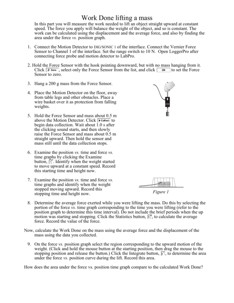
Work Done lifting a mass In this part you will measure the work needed to lift an object straight upward at constant speed. The force you apply will balance the weight of the object, and so is constant. The work can be calculated using the displacement and the average force, and also by finding the area under the force vs. position graph. 1. Connect the Motion Detector to DIG/SONIC 1 of the interface. Connect the Vernier Force Sensor to Channel 1 of the interface. Set the range switch to 10 N. Open LoggerPro after connecting force probe and motion detector to LabPro. 2. Hold the Force Sensor with the hook pointing downward, but with no mass hanging from it. Click , select only the Force Sensor from the list, and click to set the Force Sensor to zero. 3. Hang a 200 g mass from the Force Sensor. 4. Place the Motion Detector on the floor, away from table legs and other obstacles. Place a wire basket over it as protection from falling weights. Dual-Range Force Sensor 5. Hold the Force Sensor and mass about 0.5 m above the Motion Detector. Click to begin data collection. Wait about 1.0 s after the clicking sound starts, and then slowly raise the Force Sensor and mass about 0.5 m straight upward. Then hold the sensor and mass still until the data collection stops. 6. Examine the position vs. time and force vs. time graphs by clicking the Examine button, . Identify when the weight started to move upward at a constant speed. Record this starting time and height now. 7. Examine the position vs. time and force vs. time graphs and identify when the weight stopped moving upward. Record this stopping time and height now. Figure 1 8. Determine the average force exerted while you were lifting the mass. Do this by selecting the portion of the force vs. time graph corresponding to the time you were lifting (refer to the position graph to determine this time interval). Do not include the brief periods when the up motion was starting and stopping. Click the Statistics button, , to calculate the average force. Record the value of the force. Now, calculate the Work Done on the mass using the average force and the displacement of the mass using the data you collected. 9. On the force vs. position graph select the region corresponding to the upward motion of the weight. (Click and hold the mouse button at the starting position, then drag the mouse to the stopping position and release the button.) Click the Integrate button, , to determine the area under the force vs. position curve during the lift. Record this area. How does the area under the force vs. position time graph compare to the calculated Work Done? Work Done To Stretch A Spring You will measure the work needed to stretch a spring. Unlike the force needed to lift a mass, the force done in stretching a spring is not a constant. The work can still be calculated using the area under the force vs. position graph. 1. Open LoggerPro after connecting force probe and motion detector to LabPro. You only need one graph- change axis to represent this (Force vs position). 2. Attach one end of the spring to a rigid support. Attach the Force Sensor hook to the other end. Rest the Force Sensor on the table with the spring extended but relaxed, so that the spring applies no force to the Force Sensor. 3. Place the Motion Detector about one meter from the Force Sensor, along the line of the spring. Be sure there are no nearby objects to interfere with the position measurement. Motion Detector Force Sensor Dual-Range Force Sensor Force Sensor 4. The starting point is when the spring is in a nearly relaxed state (there should just be a touch of resistance force, but “nearly” 0). Hold the end of the Force Sensor that is nearest the Motion Motion Detector as shown below. The Motion Detector Detector will measure the distance to your hand, not the Force Sensor. With the rest of your arm out of the way of the Motion Detector beam, click . On the dialog box that appears, make sure that both sensors are highlighted, and click . You will also need to “reverse direction” of motion probego to Experiment- Set Up Sensors and right click on the motion detector to get to “reverse direction”. 5. Click to begin data collection. Within the limits of the spring, move the Force Sensor and slowly stretch the spring about 35-40 cm over several seconds. Hold the sensor still until data collection stops. Do not get any closer than 40 cm to the Motion Detector. If you have done everything correctly, the motion will start at position x=0m and increase as you move towards the sensor. Repeat experiment until you get a very clean graph. 6. What function best represents the relationship between the force and the displacement of the spring? The graph of force vs. position depends on the particular spring you used, but for most springs will be a straight line. This corresponds to Hooke’s law, or F = – kx, where F is the force applied by the spring when it is stretched a distance x. k is the spring constant, measured in N/m. What is the spring constant of the spring? From your graph, does the spring follow Hooke’s law? Do you think that it would always follow Hooke’s law, no matter how far you stretched it? Why is the slope of your graph positive, while Hooke’s law has a minus sign? 7. How can the work be determined from the force and displacement graph Find the work done to stretch the spring from 0-10cm, 0-20cm, and 0-30cm. What is the trend? Determine the relationship of the work done to stretch a spring from rest as a function of k and Δx. Extensions: Combine springs in series and parallel and predict the new spring constants of these combinations.
