Beam Bridges - Design Technology
advertisement
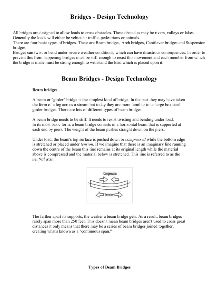
Bridges - Design Technology All bridges are designed to allow loads to cross obstacles. These obstacles may be rivers, valleys or lakes. Generally the loads will either be vehicular traffic, pedestrians or animals. There are four basic types of bridges. These are Beam bridges, Arch bridges, Cantilever bridges and Suspension bridges. Bridges can twist or bend under severe weather conditions, which can have disastrous consequences. In order to prevent this from happening bridges must be stiff enough to resist this movement and each member from which the bridge is made must be strong enough to withstand the load which is placed upon it. Beam Bridges - Design Technology Beam bridges A beam or "girder" bridge is the simplest kind of bridge. In the past they may have taken the form of a log across a stream but today they are more familiar to us large box steel girder bridges. There are lots of different types of beam bridges. A beam bridge needs to be stiff. It needs to resist twisting and bending under load. In its most basic form, a beam bridge consists of a horizontal beam that is supported at each end by piers. The weight of the beam pushes straight down on the piers. Under load, the beam's top surface is pushed down or compressed while the bottom edge is stretched or placed under tension. If we imagine that there is an imaginary line running down the centre of the beam this line remains at its original length while the material above is compressed and the material below is stretched. This line is referred to as the neutral axis. The farther apart its supports, the weaker a beam bridge gets. As a result, beam bridges rarely span more than 250 feet. This doesn't mean beam bridges aren't used to cross great distances it only means that there may be a series of beam bridges joined together, creating what's known as a "continuous span." Types of Beam Bridges A Large Box Girder Bridge Image of a Beam Bridge Beams Beams used in buildings may vary in cross sectional shape. Some may be solid or hollow. Below are three different shaped beams. The first beam is a box section, the second an I section beam and the third an L section beam. Solid beams are heavier than hollow beams. Beams like the one's below are given a special cross section for strength and rigidity. They may be as strong as the solid beams but are a lot lighter. We may describe them as having a good strength to weight ratio. Reinforced Concrete Beams Concrete beams that are used in buildings as horizontal supporting pieces above doors and windows. These are called lintels. These lintels are reinforced with steel rods cast in the concrete. The steel rods are normally placed below the neutral axis. The combination of more than one material makes the reinforced concrete a composite material. The steel enhances the strength of the concrete when stretched under tension. Concrete is very strong in compression but weak in tension. We describe this as one of the properties of concrete. Arch Bridges - Design Technology Arch bridges Arch bridges are one of the oldest types of bridges and have been around for thousands of years. Arch bridges have great natural strength. They were originally built of stone or brick but these days are built of reinforced concrete or steel. The introduction of these new materials allow arch bridges to be longer with lower spans. Instead of pushing straight down, the load of an arch bridge is carried outward along the curve of the arch to the supports at each end. The weight is transferred to the supports at either end. These supports, called the abutments, carry the load and keep the ends of the bridge from spreading out. The load at the top of the key stone makes each stone on the arch of the bridge press on the one next to it. This happens until the push is applied to the end supports or abutments, which are enbedded in the ground. The ground around the abutments is squeezed and pushes back on the abutments. For every action there is an equal and opposite reaction. The ground which pushes back on the abutments creates a resistance which is passed from stone to stone, until it is eventually pushing on the key stone which is supporting the load. Example of an arch bridge spanning a large gap. Cantilever Bridges - Design Technology Cantilever bridges normally use pairs of cantilevers back to back with a short beam bridge in between the cantilevers. Modern motorways have cantilever bridges stretching across them, they have a cantilever coming out from each side and a beam bridge in between them. The photograph above is of one of the greatest cantilever bridges the Forth Bridge. The bridge was completed in 1964 and has a main span of 3,300 feet crossing the River Forth in Scotland. The intentions for the bridge was that it would carry a railway engine and carriages up to 260 metres from the nearest support which at the time was quite an ambitious project. From the image it clear that the huge pillars take up the compression which are held up by the narrow top members. Attached to these are the complicated struts and cross bracing which withstand the forces causing buckling and twisting. The outer cantilevers have counterweights at the ends to maintain balance. The bridge was designed and built by Benjamin Baker in the late 1880's and was one of the first cantilever bridges to be constructed. This diagram shows a cantilever bridge supporting a load. Suspension Bridges - Design Technology Suspension bridges in their simplest form were originally made from rope and wood. Modern suspension bridges use a box section roadway supported by high tensile strength cables. In the early nineteenth century, suspension bridges used iron chains for cables. The high tensile cables used in most modern suspension bridges were introduced in the late nineteenth century. Today, the cables are made of thousands of individual steel wires bound tightly together. Steel, which is very strong under tension, is an ideal material for cables; a single steel wire, only 0.1 inch thick, can support over half a ton without breaking. Light, and strong, suspension bridges can span distances from 2,000 to 7,000 feet far longer than any other kind of bridge. They are ideal for covering busy waterways. With any bridge project the choice of materials and form usually comes down to cost. Suspension bridges tend to be the most expensive to build. A suspension bridge suspends the roadway from huge main cables, which extend from one end of the bridge to the other. These cables rest on top of high towers and have to be securely anchored into the bank at either end of the bridge. The towers enable the main cables to be draped over long distances. Most of the weight or load of the bridge is transferred by the cables to the anchorage systems. These are imbedded in either solid rock or huge concrete blocks. Inside the anchorages, the cables are spread over a large area to evenly distribute the load and to prevent the cables from breaking free. An image of the Golden Gate Bridge in San Fancisco. Currently, the Humber bridge in England has world's longest center span measuring 4,624 feet The diagram below shows the tension in the cables of a suspension bridge. These cables are capable of withstanding tension but offer no resistance to compression. These types of bridges work in a completely different way to the arch bridge. Structural Failure Some bridges have in the past suffered from structural failure. This may be combination of poor design and severe weather conditions. When it was opened in 1940, the Tacoma Narrows Bridge was the third longest suspension bridge in the world. It later become known as "Galloping Gertie," due to the fact that it moved not only from side to side but up and down in the wind. Attempts were made to stabilize the structure with cables and hydraulic buffers, but they were unsuccessful. Eventually on November 7, 1940, only four months after it was built the bridge collapsed in a wind of 42 mph. The bridge was designed to withstand winds of up to 120 mph. New Tacoma Narrows Bridge Some experts have blamed the collapse of the bridge upon a phenomenon called resonance. When a body vibrates at its natural frequency it can shatter. Resonance is the same force that can shatter a glass when exposed to sound vibrations from an opera singers voice. Today all new bridges prototypes have to be tested in a wind tunnel before being constructed. The Tacoma Narrows bridge was rebuilt in 1949.
