Bottom of Tub - Amazon Web Services
advertisement
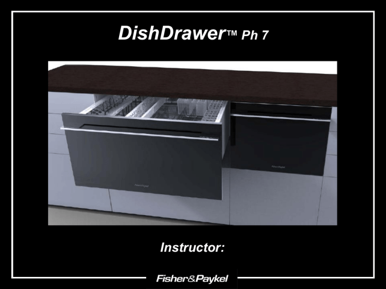
DishDrawer™ Ph 7 Instructor: Menu Models & Product Codes Components Single Integrated Diagnostics Installation Videos Review Models & Product Codes Standard Double Models DD24DCW7 Double, Classic White DD24DCX7 Double, Classic Brushed Stainless Steel DD24DI7 Double , Integrated DD24DCB7 Double, Classic Black DD24DDFX7 Double, Designer, Brushed Stainless - 88636 - 88637 - 88639 - 88641 - 88642 Standard Single Models DD24SCW7 Single, Classic White DD24SCX7 Single, Classic Brushed Stainless Steel DD24SI7 Single , Integrated DD24SCB7 Single, Classic Black DD24SDFX7 Single, Designer, Brushed Stainless - 88629 - 88630 - 88632 - 88634 - 88635 Tall Tub Double Models DD24DDFTX7 Double Designer, Brushed Stainless, Tall Tub DD24DTI7 Double Integrated, Tall Tub DD24DCTX7 Double, Classic, Brushed Stainless, Tall Tub DD24DCHTX7 Double, Classic, Brushed Stainless, Water Softener DD24DHTI7 Double, Integrated, Water Softener DD24DCTW7 Double, Tall Tub, Classic White DD24DCTB7 Double, Tall Tub, Classic Black - 88620 - 88622 - 88626 - 88638 - 88640 - 88628 - 88624 Tall Tub Single Models DD24SDFTX7 Single, Designer, Tall Tub, Brushed Stainless DD24STI7 Single, Integrated, Tall Tub DD24SCHTX7 Single, Classic, Tall Tub, Brushed Stainless Steel DD24SCTW7 Single, Tall Tub, Classic White DD24SCTB7 Single, Tall Tub, Classic Black DD24SHTI7 Single, Integrated, Water Softener, Tall Tub DD24SCTX7 Single, Classic, Tall Tub, Brushed Stainless, - 88621 - 88623 - 88631 - 88643 - 88625 - 88633 - 88627 Using the Product Code is a more accurate way to order parts and look up service manuals. It is a 5 digit code, specific to that version of the model. ® Components Key Components that ARE NOT interchangeable with previous models: All DishDrawers DD603-DD24 Front Panel DD603 Inside of Tub Bottom of Tub Cabinet Comp. • Rotor • Mains Filter Board • Heater Plate • Stator • Controller DD605 • Controller • Lids • Actuators • Spray Arms DD24 Both • Rotor • Controller, Ph. 6 • Stator • Heater Plate • Controller, Ph. 7 • Chassis Module ® Front Panel Inside of Tub Components Bottom of Tub Cabinet Comp. Front Panel Front Panel Inside of Tub Handle/Display Bottom of Tub Cabinet Comp. Rinse Aid & Detergent Dispenser Drying Fan Controller Handle/Display Front Panel Inside of Tub Back of control Bottom of Tub Housing Wedge Cabinet Comp. LCD Board Housing Harness ® Controller/Light Pipes Front Panel Inside of Tub Bottom of Tub Cabinet Comp. ® Detergent and Rinse Aid Dispenser Front Panel Inside of Tub Bottom of Tub Old Design Cabinet Comp. New Design ® Drying Fan Flap Valve Front Panel Inside of Tub Bottom of Tub Cabinet Comp. ® Badge Isolator & Wireless Receiver Only On Integrated models Front Panel Inside of Tub Bottom of Tub Cabinet Comp. Badge Isolator Wireless Receiver ® Inside of Tub Lift back of rack out first to remove Filter Plate & Spray Arm Rotor & Heater Plate Front Panel Inside of Tub Bottom of Tub Rack & Silverware Basket Cabinet Comp. Touch Switches ® Touch Switches Standard Control Front Panel “U” Program/Advance code Eco 8 4 2 1 Inside of Tub Bottom of Tub Cabinet Comp. Fault Codes 1 + 8 = 9 E9 ® Rack & Silverware Basket Front Panel Inside of Tub Bottom of Tub Cabinet Comp. ® Filter Plate & Spray Arm Front Panel Inside of Tub Bottom of Tub Sluicing jets Cabinet Comp. Strainer Hood ® Rotor/Heater Plate “O”-ring Heater Plate Front Panel Gravity Fuse Inside of Tub Bottom of Tub Cabinet Comp. DD605 & DD24 sump area PCB w/Thermistor “Land” Locknut Old DD603 sump area ® Bottom of Tub Stator/Hall Sensor Front Panel Inside of Tub Bottom of Tub Cabinet Comp. ® Stator/Hall Sensor (RPS) Front Panel Inside of Tub Bottom of Tub Cabinet Comp. ® Cabinet Components Front Panel Lid Components Inside of Tub Bottom of Tub The Service Summary is now located behind the top drawer. Link Supports Cabinet Comp. Mains Filter Board (Chassis Module) ® Lid Components Lid Front Panel Inside of Tub Bottom of Tub Yokes Actuator Cabinet Comp. Actuator connects to Yokes Actuator slides off of rails Unplugs right at actuator Yoke Extender for Tall Drawer ® Mains Filter Board/Inlet Valve Cover Front Panel Mains Filter (Chassis Module) Inside of Tub Bottom of Tub Cabinet Comp. Flood Sensor Inlet Valve ® Link Support Front Panel Inside of Tub Bottom of Tub Cabinet Comp. ® Single Integrated DishDrawer ® Changes & Benefits – Remote Control Kitchen industry wanted seamless integration, with no badge. Double remote, Single has one button. Program/Advance Eco Option Change in user interface “Play” Exposure to water indicator White dot indicates no contact with water. Red dot indicates exposure to water. ® Pairing The Remote & Wireless Receiver Transmit LED indicator Top Tub start button on doubles. Single tub start button on singles Battery Level LED Indicator Bottom Tub start button on doubles ® Gapless Door & Single Venting Venting Solution for Singles, vent through Kick-strip (No, water does not pool here, due to higher fan speed and the insulated vent hose) Only on: All Integrated Singles, Tall Designer Singles (DD36, DD24) Duct Hose Elbow Manifold ® Gapless Door Adjustment ® Cycle Profiles On Integrated models 4 things are done to • Pre-Wash cycles have been removed in all cycles to better accommodate the use of tablet detergents. reduce moisture at the exhaust: 1. The final rinse temperature is reduced 2. There is a 30 minute dwell period before the drying fan comes on. 3. The drying fan blows faster 4. The vent hose is insulated. ® Diagnostics 4 Key Steps to Diagnosing Problems 1. Talk to the customer. 2. Check for fault codes. 3. Test Components in Hardware Output. 4. Check Resistance of Components at Controller. Diagnostics – Fault History LOCK and the START/PAUSE Power Start/Pause Lock START/PAUSE button, which will then display (3 seconds each) the following: Current Fault Current Fault sub code Previous Fault Previous Fault sub code ® Diagnostics - Hardware Output “Start/Pause” to scroll Press Power Button Enter Diagnostics “Lock” to energize. “Bubbles” indicate the component is “on” Backlight Heater Lid Motors Detergent Diverter Rotor – Wash Mode Rotor- Drain Mode Rinse Aid Dispenser Drying Fan Water Softener Diverter AidWater pumpTemperature used as valve Current Water Softener Brine Pump Water Softener Brine Valve Rinse Fill Valve LED Light Controller Rail Voltage ® Diagnostics – Testing Components 8 main components can be tested right at the controller. Temperature Sensor – Power Harness – Contacts 1 & 2: 12 k Ohms @ 68°F Element – Power Harness and plug – Contact 6 & Neutral on plug: 24 Ohms +/- 3 Dropper Resistor – Power Harness – Contacts 4 & 5: 24 Ohms +/- 3 Lid Motors – Chassis Harness – Contacts 6 & 7, 8 & 9: Check if open or short circuit Fill Valve – Chassis Harness – Contact 10 & 11: 65 Ohms Motor Phases – Motor Harness – Contacts 1 & 2, 2 & 3, 1& 3: 16 Ohms phase to phase. Detergent Diverter/ Rinse Aid – Dispenser Harness – Contacts 1 & 2, 3 & 4: 65 Ohm +/- 10 Fan – Fan Harness – Contacts 3 & 4: Check if open or short circuit ® Diagnostics – Fault/Error Codes Installation E1 E5 E9 E2 E6 EC E3 E7 U1 E4 E8 U4 U6 ® E1 - Rinse LED The flood sensor in the base has been activated for more than 20 seconds. Possible Causes: • Lid not closing • Overfilling • Foaming • Not draining • Lid seal damage • Dispenser or water softener seals leaking • Damaged water inlet or drain hoses • Leaking heater plate or motor seals, or drain o-ring seals • Yoke jammed or broken • Inlet hose to inlet valve connection loose • Inlet valve body leak • Heater plate damaged (chipped enamel) • Dry E1 - PCB mains filter, harness or connectors, electronic controller. Fault Menu ® E2 - Delicate LED The controller has not sensed the motor rotating • Foreign object has jammed the rotor • The rotor has failed • hall sensor or wiring fault at the hall sensor or controller. • The hall sensor has failed • Motor stator winding or connection open circuit. • The electronic controller has failed. • PCB mains filter has failed. Sub Codes: 01 - Rinse & Eco LED - Motor not rotating -Obstruction in motor rotor housing, Rotor seized, Hall sensor 02 - Delicate & Eco LED - Motor drawing too much current -Short in motor winding, Hall sensor 03 – Delicate, Rinse & Eco LED - Motor not drawing enough current -Open circuit winding, harness connection, Motor rotor correctly installed Fault Menu ® E3 - Fast LED The water temperature has been sensed as greater than 85°C (185°F) • The incoming water is greater than 85°C (185°F) • The element has failed closed circuit • The temperature sensor on the heater plate has failed. • The electronic controller has failed Sub Codes: 01 - Rinse & Eco LED - Over Temperature - Temperature sensor Fault Menu ® E4 - Fast LED No temperature increase has been sensed for about 4 hours while element is on. • The element is not connected • The element is failed open circuit • The temperature sensor has failed • The electronic controller has failed Sub Codes: 01 - Rinse & Eco LED – Element time out - Element track faulty 02 - Delicate & Eco LED – Dropper resistor open circuit - Dropper resistor open circuit Fault Menu ® E5 - Fast & Rinse LED’s Lid motor current too high during start • The lid is jammed up or down • The electronic controller has failed Sub Codes: 01 - Rinse & Eco LED – Not starting - Wiring to lid motor, obstruction, Controller 02 - Delicate & Eco LED – No current - Open circuit lid motor 04 – Fast & Eco LED – Not stalling - Controller, Obstruction, Wiring Fault Menu ® E6 - Fast & Delicate LED’s Fan fault • Check fan harness connector • Check if fan open or short circuit (Test fan in Hardware Output. If tone occurs, replace the fan.) • The electronic controller has failed Sub Codes: 02 - Delicate & Eco LED – Under current - Open circuit fan motor, wiring 03 – Delicate, Rinse & Eco LED – Over current -Short circuit fan motor, seized fan Fault Menu ® E7 - Fast, Delicate & Rinse LED’s Detergent diverter fault • Check harness connections • Coil is open circuit • Coil is short circuit • The electronic controller has failed Sub Codes: 02 - Delicate & Eco LED – Under current - Wiring to detergent diverter valve, open circuit 03 – Delicate, Rinse & Eco LED – Over current - Short circuit coil Fault Menu ® E8 - Normal LED Solenoid fault • Check the harness connections at each solenoid • Coil is open circuit • Coil is short circuit Sub Codes: 02 - Delicate & Eco LED – Under current - Wiring to solenoid, open circuit coil 03 – Delicate, Rinse & Eco LED – Over current - Short circuit coil, wiring to coil or controller Fault Menu ® E9 - Normal & Rinse LED Microcontroller fault • Badge isolator ( if present) • Detergent diverter valve • Check harness connections • MFB • Controller Sub Codes: 04 – Fast & Eco LED’s – ADC error - Badge isolator, controller 05 – Fast, Rinse & Eco LED’s – PSU over voltage - Harness connections, Corroded connection at controller, Detergent diverter coil 06 – Fast, Delicate & Eco LED’s – EE/12C/software reset - Controller 07 – Fast, Delicate, Rinse & Eco LED’s – PSU crowbar - Check all component terminals for damage caused by corrosion, Controller & MFB Fault Menu ® EC - Normal & Fast LED’s Communications error • Harness connections between the MFB and controller • MFB • Faulty top controller • Faulty bottom controller Fault Menu ® U1 - Heavy & Rinse LED’s Water Supply • Water turned off • Insufficient water supply pressure • Blocked water softener filter (if fitted) • Spilt rinse aid causing over foam in tub • Incorrect detergent being used • Motor rotor • The machine is siphoning • Inlet valve has failed • Controller Fault Menu ® U4 - Heavy & Fast LED’s Other tub is faulting • The other tub has a fault which is preventing operation of that tub. • No repair is required to the tub showing a U4. Fault Menu ® U6 - Heavy, Fast & Delicate LED’s Spray arm not detected • Spray arm not sitting on rotor • Insufficient water pressure Fault Menu ® Installation Installation ® Installation – Bad Installs If an extension is required, extension kit 525798 must be used, not connecting a garden hose to the “Y” connector, as seen here! This one was drained through the floor with no hi-loop and the “Y” connector was folded over. Complaint? Not draining…. ® Diagnostics Component Testing Diagnostic Changes Wireless Diagnostics Integrated Installation Videos Videos – DishDrawer Diagnostics Diagnostics Component Testing Diagnostic Changes Wireless Diagnostics Integrated Installation ® Videos – Component Testing Diagnostics Component Testing Diagnostic Changes Wireless Diagnostics Integrated Installation ® Videos – Ph 7 Diagnostic Changes Diagnostics Component Testing Diagnostic Changes Wireless Diagnostics Integrated Installation ® Videos – Wireless Badge Model Diagnostics Diagnostics Component Testing Diagnostic Changes Wireless Diagnostics Integrated Installation ® Videos – Integrated Installation Diagnostics Component Testing Diagnostic Changes Wireless Diagnostics Integrated Installation ® Components Diagnostics Installation Review Components Review 1. How can you tell the difference between a badge isolator and a wireless receiver? The wireless receiver has the part number showing on the single label. 2. Does the lid actuator still plug into the mains filter board on the Ph 7 models? No, but it can be unplugged right at the motor. 3. Is the same Controller used in all DishDrawers? No. The Controllers are distinct to each model. Use the product code to order. 4. How does the DishDrawer know when a drawer is opened or closed? An infrared light is transmitted from the controller though the light pipe on the side of the tub, through a prism mounted in the chassis trim, then back through the other light pipe to the receiver 5. What is the most important number to use when ordering parts? The Product Code, which is a 5 digit number, specific to that particular version of the model. ® Diagnostics Review 1. How do you enter Diagnostics on a Ph 7 DishDrawer with an LCD display? The same as on previous models; with the Drawer off, Press and hold the “Lock” button and then the “Start/Pause” button until all the icons appear. 2. What are 3 key changes to Ph 7 Diagnostics? “F” codes are now “E” codes, Sub codes have been added and audible alerts when testing a faulty component in Hardware Output. 3. What does an E9 fault indicate? It is a microcontroller fault, usually related to the badge isolator, detergent diverter or harness, mains filter board, or the main controller. 4. Which components can be tested right at the controller? The element components, both lid motors, detergent diverter and rinse aid pump, fill valve, fan, and all phases of the motor 5. What cycle should be run after any repair? The Fast Cycle, which tests the lid motors, fill valve, detergent diverter, wash motor, element, drain motor and drying fan. ® Installation Review 1. What problems can occur because of a DishDrawer not being installed properly? Wash problems, Leaking, Draining, Drawer closure, and many more. 2. What must the minimum height of the high-loop be? The high-loop must be a minimum of 29 1/2 “ from the floor. 3. What is the minimum amount of screws that must be used to fasten the DishDrawer? At least two screws on one side. 4. Can the drain line be extended? Yes, but part # 525798 must be used. 5. What 4 things prevent excess moisture from being exhausted from integrated models? 1. Final rinse temp reduced. 2. 30 minute pause before fan comes on. 3. Higher fan speed. 4. Insulated vent hose. ® End/Return to Menu
