Uploaded by
Civil Engineers Online Academy (CEA)
Bernoulli Equation Applications: Pitot, Venturi
advertisement
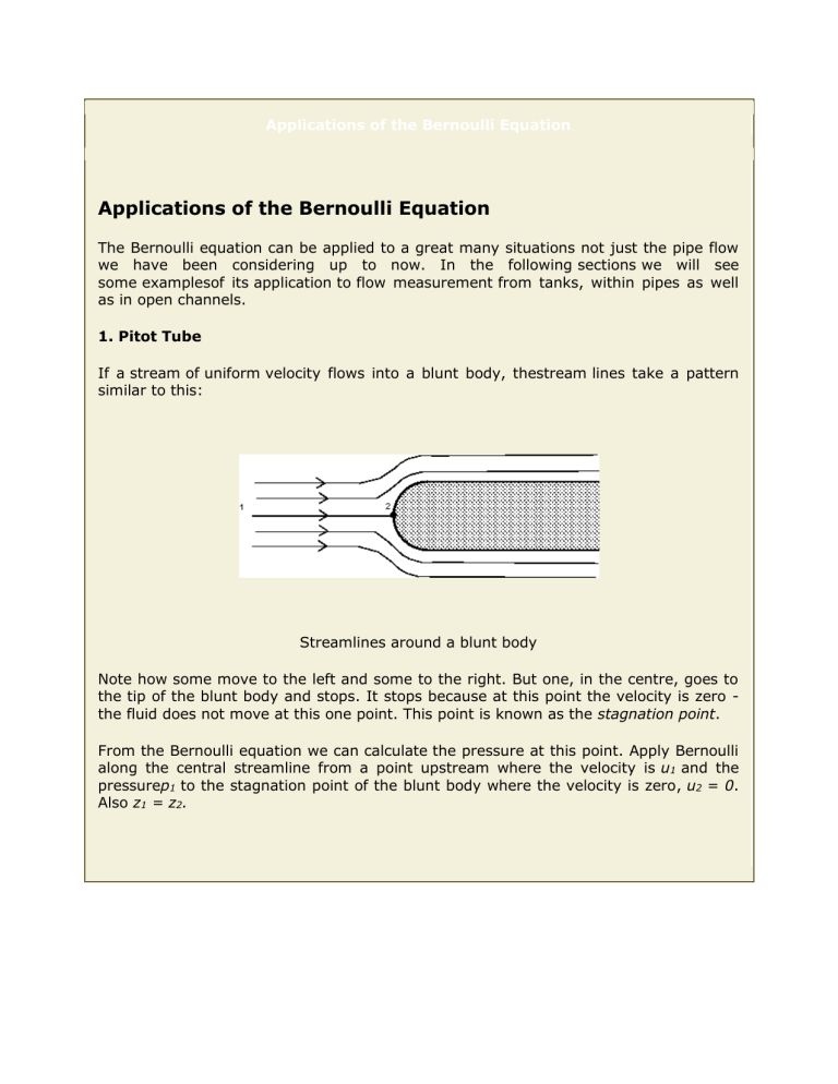
Applications of the Bernoulli Equation Applications of the Bernoulli Equation The Bernoulli equation can be applied to a great many situations not just the pipe flow we have been considering up to now. In the following sections we will see some examplesof its application to flow measurement from tanks, within pipes as well as in open channels. 1. Pitot Tube If a stream of uniform velocity flows into a blunt body, thestream lines take a pattern similar to this: Streamlines around a blunt body Note how some move to the left and some to the right. But one, in the centre, goes to the tip of the blunt body and stops. It stops because at this point the velocity is zero the fluid does not move at this one point. This point is known as the stagnation point. From the Bernoulli equation we can calculate the pressure at this point. Apply Bernoulli along the central streamline from a point upstream where the velocity is u1 and the pressurep1 to the stagnation point of the blunt body where the velocity is zero, u2 = 0. Also z1 = z2. This increase in pressure which bring the fluid to rest is called the dynamic pressure. Dynamic pressure = or converting this to head (using ) Dynamic head = The total pressure is know as the stagnation pressure (ortotal pressure) Stagnation pressure = or in terms of head Stagnation head = The blunt body stopping the fluid does not have to be a solid. I could be a static column of fluid. Two piezometers, one as normal and one as a Pitot tube within the pipe can be used in an arrangement shown below to measure velocity of flow. A Piezometer and a Pitot tube Using the above theory, we have the equation for p2 , We now have an expression for velocity obtained from two pressure measurements and the application of the Bernoulli equation. 2. Pitot Static Tube The necessity of two piezometers and thus two readings make this arrangement a little awkward. Connecting the piezometers to a manometer would simplify things but there are still two tubes. The Pitot static tube combines the tubes and they can then be easily connected to a manometer. A Pitot static tube is shown below. The holes on the side of the tube connect to one side of a manometer and register thestatic head, (h1), while the central hole is connected to the other side of the manometer to register, as before, thestagnation head (h2). A Pitot-static tube Consider the pressures on the level of the centre line of the Pitot tube and using the theory of the manometer, We know that , substituting this in to the above gives The Pitot/Pitot-static tubes give velocities at points in the flow. It does not give the overall discharge of the stream, which is often what is wanted. It also has the drawback that it is liable to block easily, particularly if there is significant debris in the flow. 3. Venturi Meter The Venturi meter is a device for measuring discharge in a pipe. It consists of a rapidly converging section which increases the velocity of flow and hence reduces the pressure. It then returns to the original dimensions of the pipe by a gently diverging 'diffuser' section. By measuring the pressure differences the discharge can be calculated. This is a particularly accurate method of flow measurementas energy loss are very small. A Venturi meter Applying Bernoulli along the streamline from point 1 to point 2 in the narrow throat of the Venturi meter we have By the using the continuity equation we can eliminate the velocity u2, Substituting this into and rearranging the Bernoulli equation we get To get the theoretical discharge this is multiplied by the area. To get the actual discharge taking in to account the losses due to friction, we include a coefficient of discharge This can also be expressed in terms of the manometer readings Thus the discharge can be expressed in terms of the manometer reading::
