- DITEK Surge Protection
advertisement
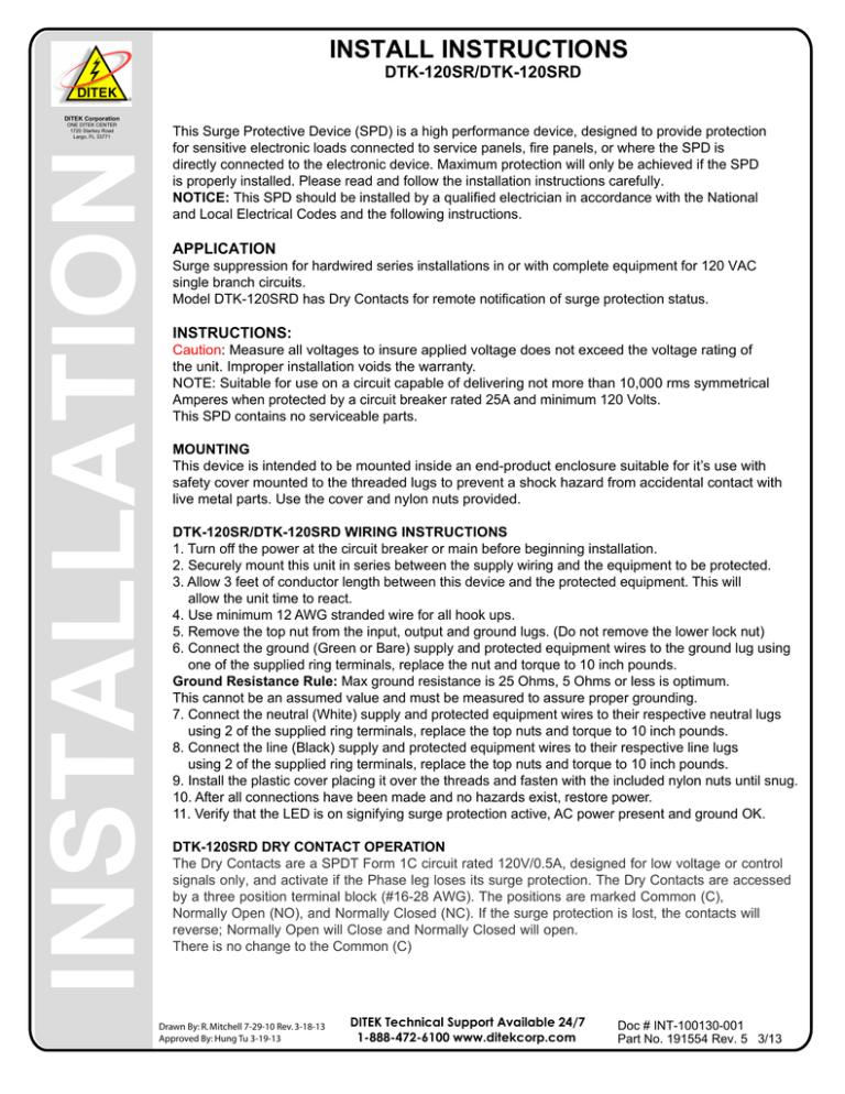
INSTALL INSTRUCTIONS DTK-120SR/DTK-120SRD DITEK Corporation This Surge Protective Device (SPD) is a high performance device, designed to provide protection for sensitive electronic loads connected to service panels, fire panels, or where the SPD is directly connected to the electronic device. Maximum protection will only be achieved if the SPD is properly installed. Please read and follow the installation instructions carefully. NOTICE: This SPD should be installed by a qualified electrician in accordance with the National and Local Electrical Codes and the following instructions. INSTALLATION ONE DITEK CENTER 1720 Starkey Road Largo, FL 33771 APPLICATION Surge suppression for hardwired series installations in or with complete equipment for 120 VAC single branch circuits. Model DTK-120SRD has Dry Contacts for remote notification of surge protection status. INSTRUCTIONS: Caution: Measure all voltages to insure applied voltage does not exceed the voltage rating of the unit. Improper installation voids the warranty. NOTE: Suitable for use on a circuit capable of delivering not more than 10,000 rms symmetrical Amperes when protected by a circuit breaker rated 25A and minimum 120 Volts. This SPD contains no serviceable parts. MOUNTING This device is intended to be mounted inside an end-product enclosure suitable for it’s use with safety cover mounted to the threaded lugs to prevent a shock hazard from accidental contact with live metal parts. Use the cover and nylon nuts provided. DTK-120SR/DTK-120SRD WIRING INSTRUCTIONS 1. Turn off the power at the circuit breaker or main before beginning installation. 2. Securely mount this unit in series between the supply wiring and the equipment to be protected. 3. Allow 3 feet of conductor length between this device and the protected equipment. This will allow the unit time to react. 4. Use minimum 12 AWG stranded wire for all hook ups. 5. Remove the top nut from the input, output and ground lugs. (Do not remove the lower lock nut) 6. Connect the ground (Green or Bare) supply and protected equipment wires to the ground lug using one of the supplied ring terminals, replace the nut and torque to 10 inch pounds. Ground Resistance Rule: Max ground resistance is 25 Ohms, 5 Ohms or less is optimum. This cannot be an assumed value and must be measured to assure proper grounding. 7. Connect the neutral (White) supply and protected equipment wires to their respective neutral lugs using 2 of the supplied ring terminals, replace the top nuts and torque to 10 inch pounds. 8. Connect the line (Black) supply and protected equipment wires to their respective line lugs using 2 of the supplied ring terminals, replace the top nuts and torque to 10 inch pounds. 9. Install the plastic cover placing it over the threads and fasten with the included nylon nuts until snug. 10. After all connections have been made and no hazards exist, restore power. 11. Verify that the LED is on signifying surge protection active, AC power present and ground OK. DTK-120SRD DRY CONTACT OPERATION The Dry Contacts are a SPDT Form 1C circuit rated 120V/0.5A, designed for low voltage or control signals only, and activate if the Phase leg loses its surge protection. The Dry Contacts are accessed by a three position terminal block (#16-28 AWG). The positions are marked Common (C), Normally Open (NO), and Normally Closed (NC). If the surge protection is lost, the contacts will reverse; Normally Open will Close and Normally Closed will open. There is no change to the Common (C) Drawn By: R. Mitchell 7-29-10 Rev. 3-18-13 Approved By: Hung Tu 3-19-13 DITEK Technical Support Available 24/7 1-888-472-6100 www.ditekcorp.com Doc # INT-100130-001 Part No. 191554 Rev. 5 3/13 INSTALL INSTRUCTIONS DTK-120SR/DTK-120SRD Illustrations Page DITEK Corporation INSTALLATION ONE DITEK CENTER 1720 Starkey Road Largo, FL 33771 120 VAC Power In. Enclosed In Conduit. Supply Wiring INPUT OUTPUT LINE LINE NEUTRAL 120 VAC Power To Protected Equipment. NEUTRAL GROUND 3' Of Conductor Length DTK-120SRD EXAMPLE REMOTE MONITORING USING FACP FOR NOTIFICATION 25 Amp Max DRY CONTACT NO C NC EXAMPLE MONITORING CIRCUIT 120VAC(+) NEUTRAL(-) LOAD: 120VAC, 0.5AMP (MAX) (L) BLK.1 SPD IN SUPPLY (L) BLK.1 (N) WHT. (N) WHT. (G) GRN. (G) GRN. OUT EQUIPMENT GND. EXPECTED SYSTEM VOLTAGES 120 VAC VOLTAGES L-N L-G N-G 120 120 0 Drawn By: J.Ramirez/R. Mitchell 7-29-10 Approved By: R. Mitchell 7-29-10 DITEK Technical Support Available 24/7 1-888-472-6100 www.ditekcorp.com Doc # INT-100130-001 Part No. 191554 Rev. 5 3/13
