240 VAC Single Phase Solar Wiring Diagram
advertisement
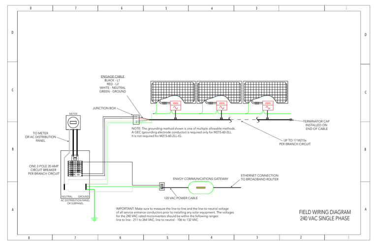
8 7 6 5 4 1 3 D D ENGAGE CABLE BLACK - L1 RED - L2 WHITE - NEUTRAL GREEN - GROUND C C JUNCTION BOX METER TERMINATOR CAP INSTALLED ON END OF CABLE NOTE: The grounding method shown is one of multiple allowable methods. A GEC (grounding electrode conductor) is required only for M215-60-2LL. It is not required for M215-60-2LL-IG. TO METER OR AC DISTRIBUTION PANEL UP TO 17 M215s PER BRANCH CIRCUIT B B ONE 2-POLE 20 AMP CIRCUIT BREAKER PER BRANCH CIRCUIT ENVOY COMMUNICATIONS GATEWAY GROUND NEUTRAL ETHERNET CONNECTION TO BROADBAND ROUTER 120 VAC POWER CABLE AC DISTRIBUTION PANEL OR SUBPANEL IMPORTANT: Make sure to measure the line-to-line and the line-to-neutral voltage of all service entrance conductors prior to installing any solar equipment. The voltages for the 240 VAC rated microinverters should be within the following ranges: line to line - 211 to 264 VAC, line to neutral - 106 to 132 VAC . A 8 7 6 5 4 FIELD WIRING DIAGRAM 240 VAC SINGLE PHASE 3 2 1 A

