TCR-HF brochure - Ticer Technologies
advertisement
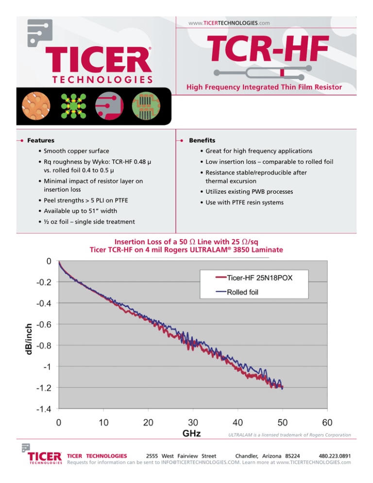
www.ticertechnologies.com High Frequency Integrated Thin Film Resistor TM Features Benefits • Smooth copper surface • Great for high frequency applications • Rq roughness by Wyko: TCR-HF 0.48 µ vs. rolled foil 0.4 to 0.5 µ • Low insertion loss – comparable to rolled foil • Minimal impact of resistor layer on insertion loss • Peel strengths > 5 PLI on PTFE • Resistance stable/reproducible after thermal excursion • Utilizes existing PWB processes • Use with PTFE resin systems • Available up to 51” width • ½ oz foil – single side treatment Insertion Loss of a 50 Ω Line with 25 Ω/sq Ticer TCR-HF on 4 mil Rogers ULTRALAM® 3850 Laminate ULTRALAM is a licensed trademark of Rogers Corporation TICER TECHNOLOGIES 2555 West Fairview Street Chandler, Arizona 85224 480.223.0891 Requests for information can be sent to INFO@TICERTECHNOLOGIES.COM. Learn more at www.ticertechnologies.com www.ticertechnologies.com High Frequency Integrated Thin Film Resistor A d v a n ta g e s Versatility – TCR-HF is optimized to achieve maximum performance when used with PTFE resin systems. Greater Uniformity – Thickness of the resistive layer is precisely controlled utilizing a proven vacuum metallization process. Precision vacuum metallization targets ensure uniform ratios of the elements in the deposited alloy, resulting in minimal resistance variation. The resistance is isotropic and is not dependent on the machine or grain direction of the copper foil or resistive layer. Product Performance and Predictability – Ticer Technologies has gone to great lengths to profile the change in resistance of TCR-HF foil during lamination. The changes pertaining to specific laminate materials and lamination conditions are well understood. This predictability ensures the product provided to our customers is consistent lot-to-lot and sheet-to-sheet. Better Resistor Tolerances – Final etch tolerances benefit from TCR-HF’s thin and uniform resistive layer. TCR-HF can eliminate laser trim requirements in all but the most precisely toleranced resistors. Reduces Fabrication Steps – TCR-HF with Nickel Chromium (NiCr) resistor alloy reduces fabrication steps by eliminating the need for a separate resistive layer etch. TCR-HF can be etched first in cupric chloride followed by ammoniacal etchant. An alternative etch for NiCr is acidic permanganate. Excellent Thermal Stability – NiCr is well known for its excellent thermal stability under continuous load and thermal excursion. The material can be subjected to multiple thermal excursions, such as lead free reflow, with minimal resistance change and ensured long term reliability. The thermal stability of TCR-HF makes it the choice for designers and users with exacting thermal stability requirements. s p e cificati o n s f o r tcr - hf TCR-HF is available in a variety of foil widths using 0.5 oz Grade 3 copper foil. TCR-HF Specification Data Set: Resistive Foil Specifications Resistive material NiCr Sheet resistance (Ω/sq) 25, 50, 100 Sheet resistivity tolerance (%) ±5 Temperature coefficient of resistance (ppm/°C) <110 Base copper foil thickness (microns) 18 Width maximum mm (inches) 1295 (51) Maximum recommended power dissipation at 40° C (watts/sq in) 25 Ω/sq: 250 50 Ω/sq: 200 100 Ω/sq: 150 — Recommended etching solutions 1st etch 2nd etch 3rd etch Cupric chloride Ammoniacal — Base foil properties meet IPC Standard 4562 for Grade 3 copper foil. Ticer Technologies’ trademark is owned by Ticer Technologies, L.L.C., Chandler, AZ. • TCR is a registered trademark owned by Nippon Mining & Metals Co., Ltd., Tokyo, Japan. • Ticer Technologies is a licensee of the technology and trademark of TCR®. • TCR® is manufactured under license from Nippon Mining & Metals Co., Ltd. using one or more of the following United States patents: 6,771,160; 6,824,880; 6,841,084; 6,489,034; 6,489,035; and 6,622,374.

