2006-03-10
advertisement
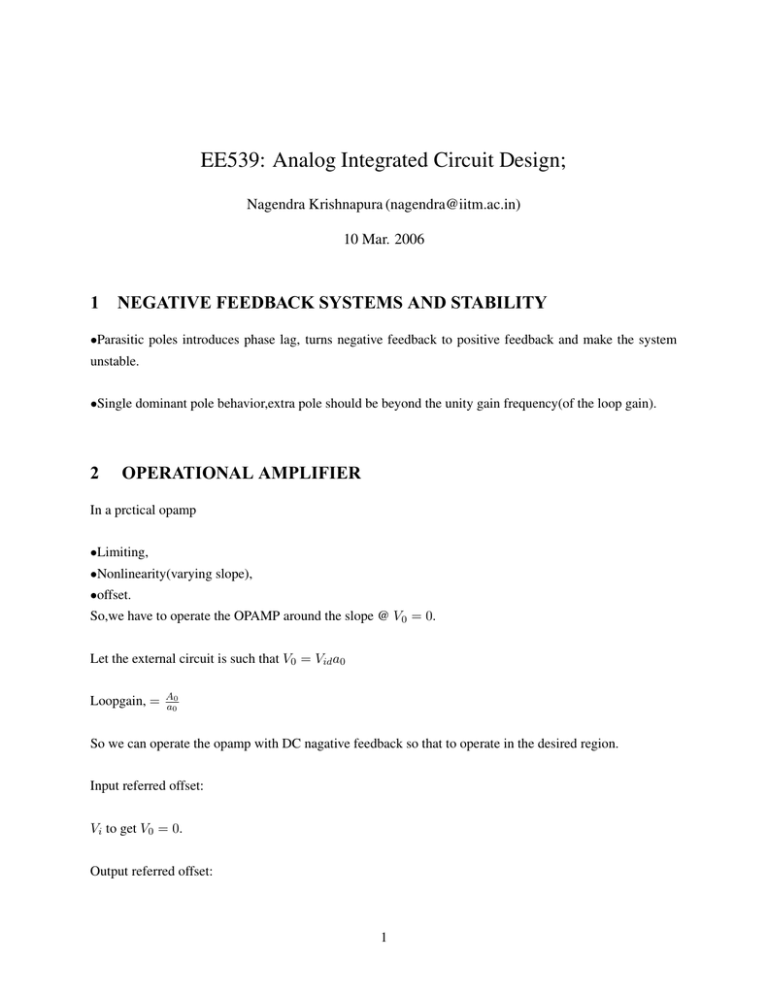
EE539: Analog Integrated Circuit Design; Nagendra Krishnapura (nagendra@iitm.ac.in) 10 Mar. 2006 1 NEGATIVE FEEDBACK SYSTEMS AND STABILITY •Parasitic poles introduces phase lag, turns negative feedback to positive feedback and make the system unstable. •Single dominant pole behavior,extra pole should be beyond the unity gain frequency(of the loop gain). 2 OPERATIONAL AMPLIFIER In a prctical opamp •Limiting, •Nonlinearity(varying slope), •offset. So,we have to operate the OPAMP around the slope @ V0 = 0. Let the external circuit is such that V0 = Vid a0 Loopgain, = A0 a0 So we can operate the opamp with DC nagative feedback so that to operate in the desired region. Input referred offset: Vi to get V0 = 0. Output referred offset: 1 2 IDEAL V0 IDEAL OPAMP: PRACTICAL A0 Vid V0 Vos Vid Figure 1: CHARACTERISTICS OF AN OPAMP: V0 Vos Vid 1/a0 Figure 2: CHARACTERISTICS OF AN OPAMP: V0 to get Vi = 0. Let an opamp with dc gain A0 = ∞,input offset Vos , and dc nagative feedback. The operating point under these conditions is, V0 = vos a0 Vid = Vos 3 V0 Vid Vos 1/a0 Figure 3: CHARACTERISTICS OF AN OPAMP: 3 SIGNS OF OPAMP TO PROVIDE NEGATIVE FEEDBACK IN A LOOP: 3.1 For an ideal opamp, current flowing through the input terminal is zero;even if V id = 0, V0 can be any value. For fig(4),V0 = −R2 R1 .Vi R2 R1 Vi V0 Figure 4: OPAMP circuit diagram To determine the signs of opamp for negative feedback in the loop, we must write V id = f (V0 ) and Vid 1 must have nagative sign. For this, we can make Vi = 0, then Vid = V0 . R1R+R . This is positive ,so we have 2 to connect this to nagative teminal, to provide negative feedback in the loop. 4 R2 R1 Vi + V0 Figure 5: OPAMP circuit diagram Similarly, we can determine the signs for fig(6),fig(8),fig(10),and fig(12). Vdd Vi I0 Figure 6: OPAMP circuit diagram In fig(10),there are two opamps. First we have to determine the signs of one opamp assuming all other opamps are ideal.Let opamp(1),assuming opamp(2) as ideal,then R3 R1 Vid1 = −V01 . R 4 R1 +R2 So we connect this to positive terminal. Now we know the signs of opamp(1). To dermine the signs of opamp(2), 5 Vdd Vi + - I0 Figure 7: OPAMP circuit diagram 1 V01 = A0 .Vo2 R1R+R 2 3 3 Vid,2 = Vo1 . R3R+R + V 02. R3R+R 4 4 So we connect this to negative terminal of the opamp(2). For fig(12), we can dermine the signs according to the voltages at node a, and node b.And the signs of opamp is shown in the fig(13). 6 Vdd Vi I0 Figure 8: OPAMP circuit diagram Vdd Vi + I0 Figure 9: OPAMP circuit diagram 7 R3 R4 R2 2 R1 Vi V0 1 Figure 10: OPAMP circuit diagram R3 R2 R4 + R1 Vi + - Figure 11: OPAMP circuit diagram V0 8 V0 R2 R4 a b R1 R3 Figure 12: OPAMP circuit diagram R2 R1 Vi + Figure 13: OPAMP circuit diagram V0
