Simple DC Adapter Power Supply for dual polarity
advertisement
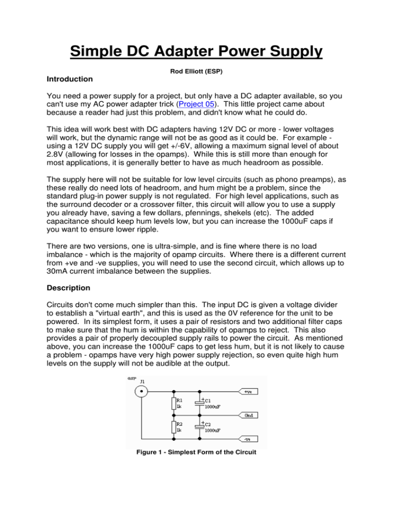
Simple DC Adapter Power Supply Rod Elliott (ESP) Introduction You need a power supply for a project, but only have a DC adapter available, so you can't use my AC power adapter trick (Project 05). This little project came about because a reader had just this problem, and didn't know what he could do. This idea will work best with DC adapters having 12V DC or more - lower voltages will work, but the dynamic range will not be as good as it could be. For example using a 12V DC supply you will get +/-6V, allowing a maximum signal level of about 2.8V (allowing for losses in the opamps). While this is still more than enough for most applications, it is generally better to have as much headroom as possible. The supply here will not be suitable for low level circuits (such as phono preamps), as these really do need lots of headroom, and hum might be a problem, since the standard plug-in power supply is not regulated. For high level applications, such as the surround decoder or a crossover filter, this circuit will allow you to use a supply you already have, saving a few dollars, pfennings, shekels (etc). The added capacitance should keep hum levels low, but you can increase the 1000uF caps if you want to ensure lower ripple. There are two versions, one is ultra-simple, and is fine where there is no load imbalance - which is the majority of opamp circuits. Where there is a different current from +ve and -ve supplies, you will need to use the second circuit, which allows up to 30mA current imbalance between the supplies. Description Circuits don't come much simpler than this. The input DC is given a voltage divider to establish a "virtual earth", and this is used as the 0V reference for the unit to be powered. In its simplest form, it uses a pair of resistors and two additional filter caps to make sure that the hum is within the capability of opamps to reject. This also provides a pair of properly decoupled supply rails to power the circuit. As mentioned above, you can increase the 1000uF caps to get less hum, but it is not likely to cause a problem - opamps have very high power supply rejection, so even quite high hum levels on the supply will not be audible at the output. Figure 1 - Simplest Form of the Circuit There will be instances where the currents from each supply will be unequal. Where this is the case, the resistor divider is not sufficient, and the +ve and -ve voltages will be unequal. By using a cheap opamp (such as a uA741), a DC imbalance between supplies of up to about 15mA will not cause a problem. However, we can do better with a dual opamp (which will cost the same or less anyway), and increase the capability for up to about 30mA of difference between the two supplies. Figure 2 - Dual Opamp Buffered Supply The 10 Ohm resistors (which can actually be almost any value that is handy from 10 to 100 Ohms) allow the opamps to share the load properly. Without these, one half of the amp (that with the higher gain) will do all the work, and the circuit will not work nearly as well. Opamp noise or other sonic characteristics are of no consequence, since their influence is completely swamped by the capacitance, so the circuit looks like a regular DC supply to the following circuitry. Very simple, but works very well. I have used this technique many times in different designs, and it is extremely effective. I found that the circuit will keep the supply balanced with as much as 40mA of unbalanced load (i.e. with up to 40mA from +ve or -ve to ground), however, this is pushing the opamp right to its limits. Note that there is no reverse polarity protection, since the diode voltage drop will reduce the limited voltage even further. If your supply is high enough in voltage (or the diode drop is not a problem for you), use a 1N4004 in series with the positive supply lead. Also, if a LED power indicator is to be used, make sure that it (and its series resistor) go between supply rails, and not to the artificial earth. This is important !
