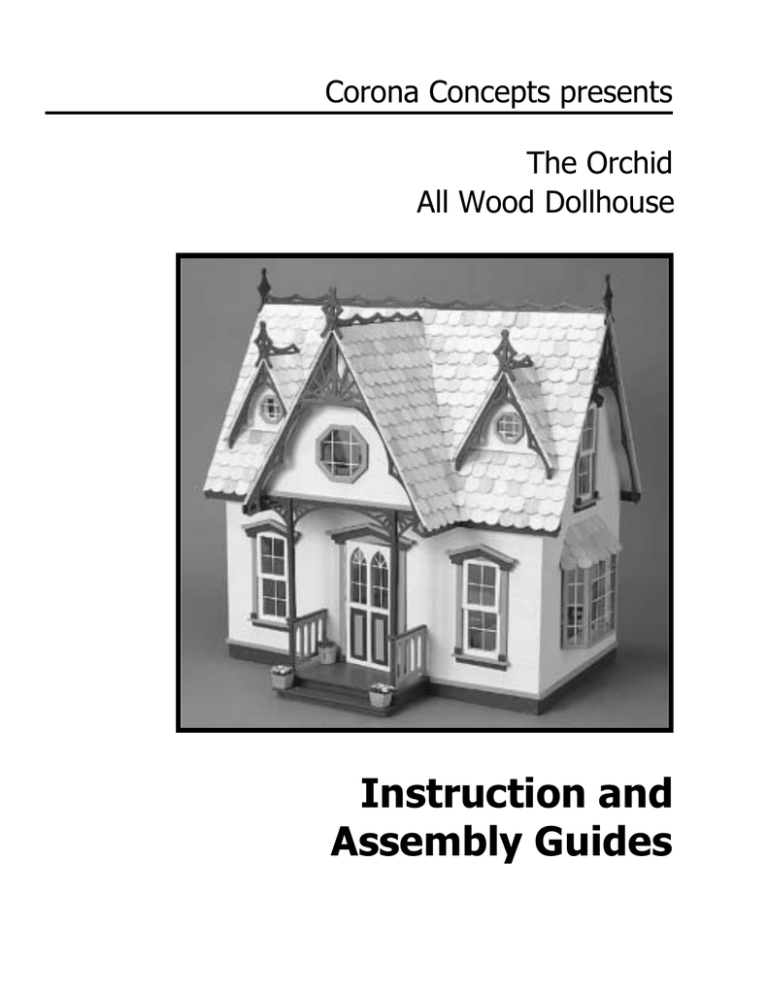
Corona Concepts presents
The Orchid
All Wood Dollhouse
Instruction and
Assembly Guides
leave a few small empty spaces for hot glue.)
In Short...Welcome to the exciting world of dollhouses
and miniatures. Since the first tab and slot die-cut dollhouse
kits arrived on the scene in the mid 1970's, their design and Tips for success!
styling concepts have evolved swiftly. However, complexity
of construction has always accompanied the great design
1. Save the kit box as a safe “nest” for the wood sheets until
and styling.
all the parts have been removed from them. Also the
photos on the outside of the box may be useful as a
As pioneers in the early days of the die-cut dollhouse
reference tool.
industry, the designers for Corona Concepts have utilized a 2. Set your work area up on a large flat surface with all of
simpler method for building dollhouses. This kit has been
your supplies at hand. Consider an area that does not
designed with efficiency in mind. It has fewer complicated
have to be “cleared” every day. Your project will take
interlocking parts, while retaining the detail and realism
some time and if assemblies can remain in place until the
necessary in the miniature industry.
paint or glue dries, it will be to your advantage.
3. Follow the instructions in order! Do NOT jump ahead or
We feel you will find that this kit will be an enjoyable and
reverse the order of assembly.
rewarding project. If you are just beginning to discover the 4. Only remove parts from the pre-cut wood sheets as they
wonderful world of miniatures, we hope that the simplicity of
are called for in the instructions. If there are parts that for
this kit will be a pleasant introduction to the craft. If you are
any reason are removed from the sheet but not called for
and experienced veteran, we hope you will appreciate the
yet, write the sheet number on the cut out and re-file or
simple, straight forward construction and design.
tape the piece to the rest of that sheet.
5. When removing pieces from the pre-cut sheets, do so
Before beginning assembly, please read through all of the
with extreme care. Some of these items are very
instructions carefully. There are tips and suggestions to aid
detailed and somewhat fragile.
you in assembly. By becoming familiar with the steps
6. The schematic diagrams are labeled with the sheet
involved and the contents of the kit, the assembly process
number, part's names, part's orientation (I.e., left, right,
will become a rewarding experience and the end product will
interior, exterior, etc.), and where the tabs and slots fir
be one you can be justly proud of.
(I.e., “front tabs” fit in piece labeled “front”). It is helpful to
write in pencil this information on the pieces before
If you should have any questions or comments during the
removing them from the sheets. All markings can easily
construction of your Orchid Dollhouse, do not hesitate to call
be erased later.
us at (800) 253-7150. We are here to answer all of your
7. The instructions contain some abbreviations and terms
questions as well as to hear your comments about our
which you will need to become familiar with:
product. Feedback from you, the customer, is our only
indication of how we're doing our job.
R&P – (Remove & Prepare) This means to remove the
Introduction
Have fun and thank you for purchasing our product!
Before You Begin
THIS KIT CONTAINS:
Ten pre-cut wood sheets
One silk-screened plastic window sheet
One set of instructions
One set of schematic diagrams
ITEMS YOU NEED TO SUPPLY:
Lead pencil and eraser
Emery board
Newspapers or other drop cloth
Masking tape
Extra sandpaper
Ruler or other straight edge
Wood filler
Stiff bristled brush
Glue (We recommend that you use a white tacky glue
as Aleenes [can be found in Walmart] or Elmer's and
hot glue only to tack. When applying white glue
specified part from the sheet by carefully punching the
piece out from the front to the back of the sheet. Prepare
the piece by carefully sanding any rough edges and
painting, staining, or otherwise decorating as desired.
(#) - Numbers in parenthesis, i.e. (8), refers to the sheet
number the piece required can be located on.
(G) – (Glue) This means that you may go ahead and glue
the piece or pieces in place.
Face Up – Means laying the item down the smooth side
up.
Face Down – Means laying the item down with the
smooth side down.
Front – The front of any sheet is that side which is
smooth and the die cut lines are clearly visible.
8. Always “dry fit” parts before gluing.
9. Paint or stain all window sashes and casings where place
window will be glued BEFORE gluing on the plastic.
10.If staining, stain first, let dry, then proceed. If painting, do
not paint tabs or inside of slots. Painting these areas will
not allow parts to fit together properly. These areas can
be touched up after assembly. Glue also tends to adhere
better to wood than to a painted surface.
11.The plastic window sheet is susceptible to scratching. It
should be protected from abrasive surfaces at all times.
12.Right and left are viewed from the front of the house.
Finishing Touches
Finishing your dollhouse is only limited by your imagination.
Paint, wallpaper, stain and stucco are only a few of the items
you can be creative with.
Wood fill and primer can be very helpful. Use the wood fill to
smooth joints between tabs and slots and on corner seams.
Primer is recommended to prime the wood with before
painting. Parts to be stained should NOT be primed.
Satin finish latex house paint will give a better result than
either flat or gloss finish.
Be sure to check your local craft shop for other decorative
items such as siding, floor tiles, carpet, electrification kits,
furniture, etc.
IF ANYTHING IS MISSING CONTACT US AT
800-253-7150
More Tips for Success!
A well lit work area will work best!
Don't glue anywhere except as specifically noted.
Empty cans or containers will help keep things
organized.
Remember to use white glue when assembling
plastic windows!
A foam brush works best for staining!
Sanding is easier if you wrap your sandpaper
around a block of wood!
Hot melt glue & glue guns may be found at your
local hardware or craft store.
Assembly Instructions
A) ASSEMBLY OF DOUBLE HUNG SASHES &
CASINGS, DORMER CASINGS, GABLE
CASINGS, FRONT DOOR WINDOWS & TRIM,
AND BAY WINDOW CASINGS
1. R&P eight double hung window sashes (8). Four are
interior, four are exterior. Remove eight double hung
windows from plastic window sheet. Position sashes
face down and position plastic window centered on
sashes – (G).
2. R&P two dormer window casings (3,6,7). Two are
interior, two are exterior. We will be using just the two
exterior for now. Remove dormer window from plastic
window sheet. Position casings face down and position
plastic windows centered on casings – (G).
Large door trim piece (with window attached) and front
door (3) can now be assembled. Lay front door face
down and position large trim piece over it – (G).
The two small rectangular panels are centered in the
lower half of the front door rectangular cut outs – (G). Set
aside front door.
3. R&P one gable window casing (2). Use exterior casing.
Remove gable window from plastic window sheet.
Position gable casing face down and position plastic
window centered on casing – (G).
5. R&P bay window casings (2,5). Note and mark with
pencil interior and exterior casings. Lay the two small
and one large exterior casings face down. Remove the
two small and one large bay windows from the plastic
sheet. Center each on the exterior casings – (G).
4. R&P front door (3) and front door trim (6). Remove front
door window from plastic window sheet. Position front
door trim (the large door overlay) face down and center
window on the arched openings – (G).
6. When dry – test fit the bay window interior casings to the 1. R&P front (3), left side (4), and right side (5). Lay these
backs of the exterior casings. Note that one side of the
pieces face down and position one double hung sash
small casings is wider than the other. Position interior
over the BOTTOM opening of each window cut out in
casings so that the inside of the window cutouts are flush
front and both sides – (G).
and there is a recessed edge along each outside of the
interior casings – (G).
2. Turn the front and side panels face up and position one
double hung sash over the TOP opening of each window
cut out – (G).
7. Lay aside all glued windows and allow to dry.
B) ASSEMBLY OF GLUED WINDOW SASHES
AND CASINGS TO HOUSE
NOTE: To achieve the “double hung” effect, part of the
house structure itself becomes one half of the window sash.
Therefore, that portion of the wood surrounding the window 3. R&P porch gable front (6) and dormers (3). Lay gable
opening, both interior and exterior, should be finished as the
and dormers face up and position the gable and dormer
sashes have been (i.e., paint or stain) before gluing the sash
window casings (the ones with the plastic windows)
in place.
centered on the window cut outs – (G). Turn gable and
dormers face down. Using prepared interior gable and
dormer casings, position the casings centered on the
window cut outs – (G).
4. R&P window casings (3,6,7). There are eight of these. 7. R&P the window casing bottoms (2). There are four of
Four interior, four exterior – they are all identical. Lay the
these – all exterior. Position the casing bottoms under
front, the left, and the right sides face up and position
and centered on the window sills – (G).
four exterior casings around the four window openings.
Center the lower legs of the casings equal distance from
the lower window cut out. This space forms the lower
window sash – (G).
8. R&P the window corner blocks (4,5). There are ten of
these. Eight are required, and there are two extra. R&P
the double hung window pediments (7,9) and pediment
5. Turn the front and side panels face down. Position the
caps (6). Position each corner block on the lower legs of
remaining interior casings over the four window cut outs.
the window casings, resting on sills – (G).
Keep the lower legs of the casings level with the bottom
edge of the interior window sash – (G).
6. R&P the window sills (2). There are eight of these. Four
interior, four exterior. They are all identical. Lay the
front, left and right side panels face down. Position four
interior sills on edge, under and centered on the interior
window casings – (G). Turn the front and side panels
face up. Position the remaining four sills on edge under
and centered on the exterior window casings – (G).
Position pediment caps on the window pediments, top
edges flush – (G).
9. Position prepared pediments on top section of window
casing. Be sure pediments are positioned the same on
all four window casings – (G).
NOTE: Front door casings, interior and exterior, will
be assembled at a later point.
3. Use prepared left and right side panels. Right side has
large rectangular opening for bay window. Insert the left
side tabs on first and second floors into appropriate slots
in left side – (G). Assemble right side in same manner –
(G). Edge of sides butting to front should receive glue as
well.
C) ASSEMBLY OF HOUSE STRUCTURE
1. R&P first floor (1). Use prepared front. Insert front tabs
on first floor into first floor slots in front. Be sure floor is
flush with bottom of front door opening – (G).
4. R&P two front door casings (6). One is interior, one is
exterior. Position interior front door casing around front
door opening – (G). Exterior casing will be used at a later
point.
2. R&P second floor (2). Insert front tabs on second floor
into second floor slots in front – (G).
5. R&P attic partition and first floor partition (7). These
items are not tabbed and can be placed wherever you
wish. However, before gluing attic partition in place, fit
the front roof to the tabs on the sides and note where the
dormer cutouts are. Mark with a pencil and then position
the attic partition accordingly. Remove front roof and
proceed – (G).
of attic partition should receive glue as well.
6. R&P front roof (6). Position left and right side slots over
roof tabs on sides – (G). Short edge of attic partition
butting front roof should receive glue as well.
Using two gussets, position one gusset on each side,
under roof at apex. This covers the triangular opening –
(G).
9. R&P first floor base piece (1). Position under first floor at
rear of house. Position it flush with side edges and first
floor edge – (G).
7. R&P all gussets (3,5). There are 6 in all. Refer to
illustration and position one gusset against inside edge of
front roof, near the middle but not in gable cut out – (G).
Set aside remaining gussets.
D) ASSEMBLY OF DORMERS
8. R&P rear roof (7). Position left and right side slots over
roof tabs on sides – (G). Edge of gusset and top portion
1. R&P dormer roofs (4,5). There are two right and two left
(Each dormer will get one right and one left). Use
prepared dormer fronts and position left dormer slots
over dormer roof tabs – (G).
E) ASSEMBLY OF PORCH
1. R&P porch base front and sides (5). Butt the two side
pieces to the back of the front piece – (G). Position base
side tabs into porch base slots on the front of house –
(G).
Using one gusset per dormer, position the gusset to
inside of top edge of left dormer roof – (G). Position right
dormer roof over dormer roof tabs and gusset – (G).
Repeat for second dormer.
2. R&P porch front and side risers (5). Butt sides to back of
front – (G). Position riser unit to porch front base – (G).
2. Position assembled dormers over dormer cut outs in
front roof – (G).
3. R&P porch floor (1) and stair tread (5). Position porch
floor resting on porch base and against the front of the
house, centering on corner notches embossed on front –
(G). Position porch stair tread on stair tread riser and
centered with porch floor – (G).
4. Position prepared exterior front door casing around and
flush with front door opening in front – (G).
6. Previously assembled front door can now be hinged to
door casing or glued in position.
5. R&P front door corner blocks (4). Three are provided –
two are used. R&P front door pediment (2). R&P front
door pediment cap (6). Position corner blocks on bottom
of front door exterior casing, resting on porch floor – (G).
7. R&P porch railings (2). Position railing tabs into slots in
front of house and center front leg of railing on notches
embossed on porch floor. Smooth side of railing should
face outward – (G).
Position front door pediment cap over front door
pediment with top edges flush – (G). Position pediment
on top of front door casing – (G).
8. R&P porch railing handrails (1) and railing posts (1).
Position handrails on top edge and centered over porch
railing – (G). Position railing posts against front edge of
porch railing and centered under porch handrails – (G).
Stand porch post grillwork unit on top of porch railing
handrails, set back from front edge of handrail by
approximately 1/8”. This measurement is not exact, just
be sure that the front edge of the corner blocks are
recessed back from the edge of the handrail – (G).
9. R&P porch post grillwork (8). Use extreme care when
removing the grillwork parts from this sheet! R&P
porch post corner blocks (4). Three are provided – two
are used. Lay porch post grillwork face up and position
porch posts over each long post part of grillwork. Be
sure top and bottom ends are flush with edges of
grillwork – (G).
Stand porch post grillwork straight up and position one
corner block centered under each porch post end – (G).
10.R&P porch ceiling (1). Position ceiling face down with
front tabs in porch ceiling into slots in front of house. Top
edge of porch posts will be flush with outer edge of gable
tabs on ceiling.
When viewed from the side, the porch posts unit will be
parallel with front of house (i.e. straight up and down) –
(G).
F) ASSEMBLY OF GABLE
1. R&P gable roof left (4) and right (5). Use one gusset.
Position prepared porch gable with porch ceiling slots
over gable tabs on ceiling – (G).
Lay one stair stringer face up. Position one stair tread
into slot at opposite ends of stringer. Keep treads at 90°
to stringer. Smooth sides of treads should face the TOP
of the stringer – (G).
2. Position second stringer face up – notch towards TOP –
over tabs of first and last stair tread – (G).
Remaining treads are now inserted and glued into
remaining slots in both stringers. It is important to keep
everything as “square” as possible while assembling.
2. Position left gable roof with gable slots over roof tabs on
gable and front roof tabs in left gable roof slots in front
roof – (G). Position one gusset against inside of left
gable roof – (G). Position right gable roof on roof tabs of
gable and roof tabs in slots of front roof – (G). Apply glue
to gusset as well.
3. Position stair unit in house with top against bottom of
second floor near edge of opening.
G) ASSEMBLY OF STAIRS
1. R&P stair stringers (9) and stair treads (1,2,3). There are
two stringers and nine treads. Note the small notch in
one end of stringers denotes the TOP.
Bottom rests on first floor with side of stringer resting
against left wall of house. Bottom of stairs should be at
front of house – (G).
All recessed edges on casings are toward interior.
3. Position assembled unit over and centered on bay
window cut-out in right side of house – (G).
H) ASSEMBLY OF BAY WINDOW
1. R&P bay window top and bottom (3). Position prepared
large (center) bay window casing face down (recessed
edge on sides will be facing you). Position bay window
top, smooth side toward window, against inside edge of
interior casing, flush with top edge of casing and
centered – (G). Position bay window bottom against
inside edge of window casing, smooth side toward
window, and flush with top edge of casing – (G).
4. Before R&P of bay window roof (4), mark each roof
section as labeled in schematic (i.e. left, right, front
edge). Turn sheet #4 face down and apply masking
tape across the back of the three roof sections – in effect
hinging the left and right roof to the center section. Turn
sheet face up and proceed with R&P of roof sections.
Remove as a hinged unit.
2. Turn unit face up. Position each narrow bay window
casing to either side of large casing, butting outside edge
of large casing and flush with top and bottom – (G).
5. Position the roof unit over the bay window unit with “front
edge” outward. Allow the roof to “drape” itself over the
unit with back edges resting evenly against right side wall
and the under side resting against top of bay unit.
Remove, – (G) and set back in place.
3. R&P apex grillwork (8). There are three pieces – one left
side, one right side, and one gable. Note that these
pieces and all gingerbread pieces are recessed about
1/8” from edge of roof. Position each apex piece in the
three locations under roof edges – (G).
I) ASSEMBLY OF TRIM, GINGERBREAD AND
EAVES
1. R&P first slot trim (7). There are two side pieces and two
4. R&P main roof gingerbread (8). There are two left, and
front pieces. Position each front piece over front first
two right pieces. Each side gets one left and one right.
floor slots and top edge of trim even with porch floor –
Position each piece, butting to bottom edge of apex piece
(G). Position each side piece over first floor side slots
and recessed 1/8” from roof edge – (G).
and butting up to front trim pieces – (G).
5. R&P porch gable gingerbread (8). Position these two
pieces, left and right, as previous side pieces – (G).
2. R&P gable edge trim (4). Position trim piece so it covers
ceiling tabs and slots in bottom edge of gable. Slanted
ends rest against gable roof – (G).
6. R&P dormer gingerbread (8). Note that the left and right
pieces butt together at apex of dormer. Position each
piece, recessed 1/8” from roof edge – (G).
Finally, position gable eave boards in same manner to
gable roof edge butting flat end to the end of front eave
board – (G).
7. R&P eaves (3). There are five sets of eave boards. Four
dormer, two rear, two gable, and two front. Starting with
the dormer eaves (the smallest), position eave boards so
curved edge is to the front and bottom, flat edge butts to 8. R&P roof ridge trim (10). There are five pieces. One
lower edge of dormer roof. Slanted edge rests on front
gable, one for each dormer, and two main roof pieces.
roof, and inside surface rests against lower edge of
Note that the main roof pieces butt together in the center
gingerbread – (G).
of the roof. Position one main roof ridge trim piece in
valley created by junction of front and rear roof, outer
edge of trim flush with outer edge of roof – (G). Position
other half of main roof ridge trim on other half of roof,
flush with edge, butting first piece in the center of the roof
– (G).
Position rear eaves against lower edge of rear roof,
curved edge outward, and resting against lower edge of
gingerbread – (G). Position front eaves in similar manner
against bottom edge of front roof, curved ends outward –
(G).
Position each dormer ridge trim on top of dormers,
slanted edge resting against main roof of house – (G).
Position gable ridge trim in same manner to top of porch
gable roof – (G).
9. R&P roof finals (6,7,10). There are five of these. One
gable, two dormer, and one left and one right for main
roof. Position each final over the end of each roof ridge
trim piece. The lower legs of each final resting on each
roof surface – (G).
J) ASSEMBLY OF STAIR RAILING AND
HANDRAILS
1. R&P stair railing (11). Position small stair railing with
bottom edge even with second floor opening opposite of
top of stairs. One edge should be flush against the inside
of the left wall – (G). Position larger railing with bottom
edge even with stair opening. Inside of smaller railing
should butt against larger railing. - (G).
2. R&P stair railing handrails (11). Position smaller handrail
centered on top of smaller railing with one end butting
against the inside of the left interior wall. - (G). Position
longer handrail centered over longer railing with curved
end towards stair end of opening. Smaller handrail
should butt against the inside of the larger handrail with
the square end flush at the corner. - (G).
Shingles, shingles, shingles ....
TOOLS REQUIRED
Sharp utility knife
Hot melt glue gun and glue
Pencil and ruler or other straight edge
OPTIONAL
1” Foam brush
Wood stain
GENERAL INSTRUCTIONS
3. Carefully measure and draw parallel guidelines on the
roof panels beginning at the bottom edge of the roof.
Guidelines should be spaced apart no less than one half
the length of one shingle.
4. Guidelines MUST meet evenly at all gable intersections.
Different shingle styles are available
at your local craft store.
5. Begin applying the top edge of the shingles along the
guidelines using hot melt glue. Start at bottom edge of
roof and continue upwards to top edge of roof. Shingles
at each end of the row will need to be cut to size. Be
sure to cut and fit each shingle at the gable intersection
before gluing in place. Also keep in mind that as you
continue upwards, each row should be staggered by half
the width of one shingle.
6. The last row of shingles at the top of the edge of the roof
will need to be trimmed in length. They should be cut to
approximately half the length of one shingle and applied,
giving the roof a finished appearance.
7. OPTIONAL: Apply wood stain with foam brush using
caution not to soak the shingles too heavily as the stain
may cause the glue to loosen. If this should happen, just
allow the glue to re-harden on its own. (NOTE: You may
want to consider staining a few extra shingles in case any
are ever damaged.)
THATS IT! SIT BACK AND ADMIRE YOUR CREATION!
©2008 Corona Concepts
Schenevus, NY 12155
www.corona-concepts.com
All rights reserved
These instructions were
printed in New York State
Illustrations provided by
Ben Anderson
ben@greenleafdollhouses.com
Corona Concepts is a member of
the Greenleaf Dollhouses Family

