EUROLED
SMD 7 Segment Display
7 mm Digit Height
ED 07 Series
/1/
/2/
/3/
/4/
ED07.CC.R
ED07.CA.R
ED07.CC.YG
ED07.CA.YG
Common Cathode Red
Common Anode Red
Common Cathode Yellow-Green
Common Anode Yellow-Green
Features and Benefits
Brilliant light output
Only 4 mm total height
Withstands high solder
treatment
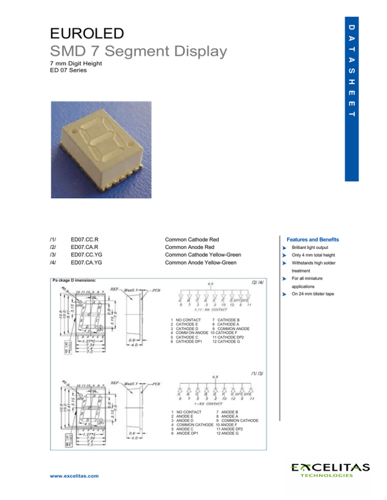
Pa ckage D imensions:
/2/ /4/
For all miniature
applications
On 24 mm blister tape
1
2
3
4
5
6
NO CONTACT
7 CATHODE B
CATHODE E
8 CATHODE A
CATHODE D
9 COMMON ANODE
COMM ON ANODE 10 CATHODE F
CATHODE C
11 CATHODE DP2
CATHODE DP1
12 CATHODE G
/1/ /3/
1
2
3
4
5
6
www.excelitas.com
NO CONTACT
ANODE E
ANODE D
COMMON CATHODE
ANODE C
ANODE DP1
7 ANODE B
8 ANODE A
9 COMMON CATHODE
10 ANODE F
11 ANODE DP2
12 ANODE G
Absolute Maximum Ratings (Ta = 25° C)
Parameter
Forward Current *3 *4
*1 *3
Pulse Forward Current
Operating Temperature
Storage Temperature
*2
Soldering Temperature
*3
Power Dissipation
Reverse Voltage
Symbol
IF
IFp
Topr
Tstg
Tsol
Pd
VR
Rating
25
160
-40 7 +105
-40 7 +105
260
60
5
Units
mA
mA
°C
°C
°C
mW
V
Notes: *1: IFP Conditions - Pulse Width < 10 msec and DC< 1/10
*2: Soldering Time < 5 s
*3: Per Segment
*4: Minimal Forward Current 5 mA
Electro - Optical Characteristics (Ta = 25° C)
Parameter
Forward Voltage
Reverse Current
Symbol
VF
IR
Condition
IF = 20 mA
VR = 5 V
-
Luminous Intensity
per segment
IV
IV
IF = 10 mA
IF = 10 mA
4.00
1.40
per dec. point
IF = 10 mA
IF = 10 mA
IF = 20 mA
2.00
0.45
Peak Wavelength
IV
IV
λp
Dominant Wavelength
λD
IF = 20 mA
λ
IF = 20 mA
Spectral Half Bandwidth
Min.
Typ.
2.00
-
Max.
2.40
10
Unit
V
µA
Type
/1/ /2/ /3/ /4/
/1/ /2/ /3/ /4/
7.50
2.30
-
mcd
mcd
/1/ /2/
/3/ /4/
3.50
0.80
632
575
624
573
20
-
mcd
mcd
nm
nm
nm
nm
nm
/1/
/3/
/1/
/3/
/1/
/3/
/1/
/2/
/4/
/2/
/4/
/2/
/4/
/2/ /3/ /4/
Figure 1
/1/ /2/
www.excelitas.com
/3/ /4/
EUROLED
2
Figure 2
Typical Electro-Optical Characteristics Curves:
/1/ /2/
www.excelitas.com
/3/ /4/
EUROLED
3
Figure 3
Soldering Heat Reliability (DIP):
Soldering Iron:
Basic spec is < 5 sec when 260° C. If temperature is higher, time should be shorter (+10° C -> -1 sec). Power
dissipation of iron should be smaller than 15 W, and temperature should be controllable.
Surface temperature of the device should be under 230° C.
Rework:
1. Customer must finish rework within 5 sec under 260° C.
2. The head of iron must not touch copper foil.
Figure 4
Reflow Temp./ Time:
www.excelitas.com
EUROLED
4
Figure 5
Package Dimensions:
Figure 6
Taping Dimensions:
Packing Quantity Specification:
1000 pcs per roll
Excelitas Technologies
European Customer
Support for LED Solutions
Luitpoldstrasse 6
85276 Pfaffenhofen, Germany
Telephone: (+49)8441-8917-0
Fax: (+49)8441-71910
generalinquiries@excelitas.com
European Headquarters
Wenzel-Jaksch-Strasse 31
65199 Wiesbaden, Germany
Telephone: (+49)611-492-247
Fax: (+49)611-492-170
North America
Customer Support Hub
22001 Dumberry Road
Vaudreuil-Dorion, Québec
Canada J7V 8P7
Telephone:(+1) 450-424-3300
(+1) 866-574-6786 (toll-free)
Fax: (+1) 450-424-3345
Asia Customer Service Hub
47 Ayer Rajah Crescent #06-12
Singapore 139947
Telephone: (+65)6775-2022
(+65)67704-366
Fax: (+65)6775-1008
For a complete listing of our global offices, visit www.excelitas.com
©2011 Excelitas Technologies Corp. All rights reserved. The Excelitas logo and design are registered trademarks of Excelitas Technologies Corp. All other trademarks not owned by Excelitas Technologies
Corp. or its subsidiaries that are depicted herein are the property of their respective owners. Excelitas reserves the right to change this document at any time without notice and disclaims liability for editorial,
pictorial or typographical errors.
600076_01 DTS1005
www.excelitas.com
EUROLED
5


