IJSTE - International Journal of Science Technology & Engineering | Volume 2 | Issue 4 | October 2015
ISSN (online): 2349-784X
Simulation of TCSC its Characteristics and
Resonance Conditions
Rajesh D. Panchal
Lecturer
Department of Electrical Engineering
R. C. Technical Institute, Ahmedabad
Abstract
The basic concept of tcsc working, impedance characteristic and single point and multi point resonance conditions can be easily
understand by Mat lab simulation of the TCSC. The single point and multi point resonance depends upon the value of inductive
reactance, capacitive reactance and resulting firing angle of the SCR. In this paper, the equivalent circuit of the TCSC, its
operation, impedance characteristic and different applications are given.
Keywords: TCSC Equivalent Circuit, Impedance Characteristic, Simulink Model And Applications
________________________________________________________________________________________________________
I. INTRODUCTION
To meet rising demand of power, it is not possible to install new power stations and erecting new transmission line in given
forecast period of the power generation. One of the ways to increase power transfer capability by using FACTS devices. The
FACTS devices are introduced either is in series or shunt with the transmission line. The series compensation offers major
advantages as compared to shunt compensation. To get same benefits as that of series capacitors, the ratings of the shunt
capacitors are approximately three to six times. The thyristor controlled series capacitor (TCSC) is a series compensation type
FACT device.
The TCSC provides following mentioned advantages: (1)rapid and continuous control of power.(2)During short circuit, the
TCSC can switch from controlled capacitor mode to controlled inductive mode thereby reducing the short circuit
current.(3)Suppress sub-synchronous oscillations.(4)Prevent loop power flow.(5)Reducing dc offset voltages.
II. OPERATION
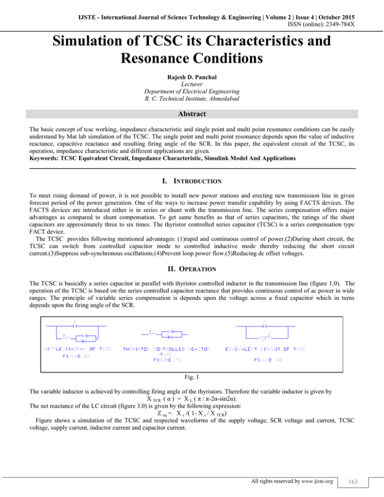
The TCSC is basically a series capacitor in parallel with thyristor controlled inductor in the transmission line (figure 1.0). The
operation of the TCSC is based on the series controlled capacitor reactance that provides continuous control of ac power in wide
ranges. The principle of variable series compensation is depends upon the voltage across a fixed capacitor which in turns
depends upon the firing angle of the SCR.
Fig. 1
The variable inductor is achieved by controlling firing angle of the thyristors. Therefore the variable inductor is given by
X TCR ( α ) = X L ( π / π-2α-sin2α).
The net reactance of the LC circuit (figure 3.0) is given by the following expression:
Z eq = X c /( 1- X c / X TCR)
Figure shows a simulation of the TCSC and respected waveforms of the supply voltage, SCR voltage and current, TCSC
voltage, supply current, inductor current and capacitor current.
All rights reserved by www.ijste.org
163
Simulation of TCSC its Characteristics and Resonance Conditions
(IJSTE/ Volume 2 / Issue 4 / 027)
A. Simulation of the TCSC:
Fig. 1: α=70 Degree for positive and 250 Degree for Negative Cycle of the Supply Voltage
III. THE TCSC: MODES OF THE OPERATION
When X c > X TCR , the capacitive reactance becomes higher than the inductive reactance, the effective reactance of the TCSC
becomes negative resulting that it behaves likes an inductor. As shown in the waveforms I L and I TCR are in the phase.
All rights reserved by www.ijste.org
164
Simulation of TCSC its Characteristics and Resonance Conditions
(IJSTE/ Volume 2 / Issue 4 / 027)
Fig. 2: Α= 160 Degree For Supply Current, Inductive Current And Capacitive Current
Similarly when X c < X TCR , the effective reactance of the TCSC becomes positive resulting that it behaves likes a capacitor. In
this condition I L and I TCR are out of phase with respect to each other.
Fig. 3: Α=70 Degree For Supply Current, Inductive Current And Capacitive Current
All rights reserved by www.ijste.org
165
Simulation of TCSC its Characteristics and Resonance Conditions
(IJSTE/ Volume 2 / Issue 4 / 027)
It should be noted that both thyristors are bypassed when they are gated for 180 degree. In this condition most of the current
flow through thyristor controlled reactor and only some current flows through capacitor branch. The net current flows through
inductor are continuous and sinusoidal. Generally this mode is used for protecting capacitor against over voltages
If the gating pulses are blocked, TCSC behaves like a simple capacitive circuit hence this mode is also known as waiting mode
of operation.
In the capacitive mode of operation, thyristors are gated such that αMIN < α < 90 in which effective value of the TCSC
reactance increases as the firing angle increases from zero. The ratio of the X TCSC / X C should be kept below 3.0 for capacitive
mode region. The impedance is lowest at firing angle of 90 degree therefore power transfer increases as the firing angle
decreases.
Similarly in the inductive mode of operation, thyristors are gated such that the TCSC reactance increases as the firing angle
decreases from 180 degree.
It is interesting to note that even though value of the TCSC reactance is same for both inductive and capacitive mode of
operation, current through TCR branch is more in inductive mode of operation. The TCR injects harmonics in addition to
fundamental frequency current resulting distortion in the capacitor voltage waveforms even though line current remains
sinusoidal.
The variation of the per unit reactance as a function of the firing angle of the thyristor is shown in the figure 4.0
Fig. 4: Per-unit reactance Versus Firing angle Characteristic
The resonance condition is shown in the characteristic of the TCSC per unit reactance versus firing angle of the Thyristor.
However, the numbers of resonance depends upon proper choice of value of K, where
K = sqrt (X C / X L )
Therefore only one resonance point is for value of C= 247.5µF and L=6.0mH .Multiple resonance do not allow because it will
reduce operating range of the TCSC. The waveforms for the two resonance is shown the figure for the value of C= 247.5µF and
L= 2.5mH and similarly for three resonance value of C = 247.5µF and L= 1.0mH.
All rights reserved by www.ijste.org
166
Simulation of TCSC its Characteristics and Resonance Conditions
(IJSTE/ Volume 2 / Issue 4 / 027)
Fig. 5: Current Waveforms for Single Resonance Condition
Fig. 6: Current Waveforms for Two Resonance Condition
All rights reserved by www.ijste.org
167
Simulation of TCSC its Characteristics and Resonance Conditions
(IJSTE/ Volume 2 / Issue 4 / 027)
Fig. 7: Current Waveforms for Single Resonance Condition
Fig. 8: Different Waveforms for Three Resonance Condition
All rights reserved by www.ijste.org
168
Simulation of TCSC its Characteristics and Resonance Conditions
(IJSTE/ Volume 2 / Issue 4 / 027)
IV. RESULTS
From the above resonance condition waveforms, it is concluded that the value of the inductance and capacitance or firing angle
of the switching devices are selected such that multiple resonances are avoided.
REFERENCES
[1]
[2]
[3]
[4]
[5]
[6]
[7]
K.R.PADIYAR: Facts controllers in power transmission and distribution
R.Mohan Mathur and Rajiv K.Verma : Thyristor based facts controllers for electrical transmission systems, IEEE press
N.G.Verma and L.Gyugyi: Understanding FACTS Concepts and Technology of Flexible AC Transmission Systems, IEEE Press
Xiao-Ping Zhang, Christian Rehtanz, Bikash Pal: Flexible AC Transmission line systems, Modeling and control by Springler
Vijay K.Sood: HVDC And FACTS Controllers, Applications of TLF eBook
Simpower Systems for use with Simulink Version 3.0
Rajesh Kumar Nema, Shailendrakumar Jain and S.Meikandasivam “Bahavoiral Study of a TCSC /Simulink Implementation” paper accepted
presentation at World academy of Science and Technology, 2008
All rights reserved by www.ijste.org
for
169


