ISSN: 2278 – 7798
International Journal of Science, Engineering and Technology Research (IJSETR)
Volume 5, Issue 5, May 2016
Modeling of Power System For Improving Stability
Using Thyristor Controlled Series Capacitor
Anil Kumar, Dr. Jyoti Shrivastava
Abstract— In a modern day’s power system have been growing
due to increase of demand and loads, it’s getting more and
more difficult to provide stability and control. Reactive power
control is the basic requirement for maintaining the voltage
levels thereby the stability of the interconnected power system.
Voltage variations can be stabilized and controlled by
providing required reactive power. These low voltages may also
reduce the power Transfer through the transmission lines and
may lead to Instability Hence FACTS Controllers are widely
used in Interconnected Power Systems to control the voltage
levels within the tolerable limits. FACTS Controllers are used
to enhance controllability and increase power transfer
capability. Among the FACTS devices, the TCSC controller
has given the best results in terms of performance and
flexibility. In this paper an overview to general type of FACTS
controller and performance of TCSC is given. TCSC are used
to improve power handling capability and reduce line losses in
power systems. An additional feature of TCSC is its dynamic
performance of power oscillation damping by varying the
power flow in accordance with power oscillations. This
behavior can be used to improve the stability of the system
following a disturbance. In this paper, stability of the power
system is improved using TCSC.
Index Terms— FACTS, Thyristor Controlled Series Capacitor,
Reactive Power Control, Stability, Power System.
I. INTRODUCTION
Electric energy is an essential ingredient for the industrial
and all round development of any country. It is a coveted
form of energy, because it can be generated centrally in bulk
and transmitted economically over long distances. Further,
for domestic and industrial applications it can be adapted
easily and efficiently. The per capita consumption of
electrical energy is a reliable indicator of a country‟s state of
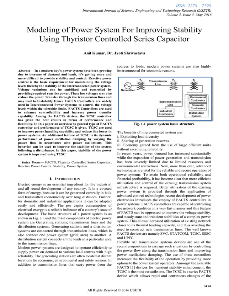
development. The basic structure of a power system is as
shown in Fig.1.1.and the main components of electric power
system are Generating stations, transmission lines and the
distribution systems. Generating stations and a distribution
systems are connected through transmission lines, which is
also connect one power system (grid, area) to another. A
distribution system connects all the loads in a particular area
to the transmission lines.
Modern power systems are designed to operate efficiently to
supply power on demand to various load centres with high
reliability. The generating stations are often located at distant
locations for economic, environmental and safety reasons. In
addition to transmission lines that carry power from the
sources to loads, modern power systems are also highly
interconnected for economic reasons.
Fig. 1.1 power system basic structure
The benefits of interconnected system are:
i. Exploiting load diversity
ii. Sharing of generation reserves
iii. Economy gained from the use of large efficient units
without sacrificing reliability.
In recent years, power demand has increased substantially
while the expansion of power generation and transmission
has been severely limited due to limited resources and
environmental restrictions. Now, more than ever, advanced
technologies are vital for the reliable and secure operation of
power systems. To attain both operational reliability and
financial profitability, it has become clear that more efficient
utilization and control of the existing transmission system
infrastructure is required. Better utilization of the existing
power system is provided through the application of
advanced control technologies recent development of power
electronics introduces the employ of FACTS controllers in
power systems. FACTS controllers are capable of controlling
the network condition in a very fast manner and this feature
of FACTS can be oppressed to improve the voltage stability,
and steady state and transient stabilities of a complex power
system. This allows increased utilization of existing network
closer to its thermal loading capacity, and thus avoiding the
need to construct new transmission lines. The well known
FACTS devices are namely SVC, STATCOM, TCSC, SSSC
and UPFC.
Flexible AC transmission systems devices are one of the
recent propositions to assuage such situations by controlling
the power flow along the transmission lines and improving
power oscillations damping. The use of these controllers
increases the flexibility of the operation by providing more
options to the power system operators. Amongst the available
FACTS [3] devices for transient stability enhancement, the
TCSC is the most versatile one. The TCSC is a series FACTS
device which allows rapid and continuous changes of the
1434
All Rights Reserved © 2016 IJSETR
ISSN: 2278 – 7798
International Journal of Science, Engineering and Technology Research (IJSETR)
Volume 5, Issue 5, May 2016
transmission line impedance. It has great application and The current in the reactor can be from maximum ( thyristor
potential in accurately regulating the power flow on a valve closed) to zero (thyristor valve open) by method of
transmission line.
firing delay angle control. It means that the closure of
thyristor value is delayed wrt the peak of applied voltage in
II. THYRISTOR CONTROLLED SERIES CAPACITOR (TCSC) each half cycle and thus the duration of current conduction
For TCSC is one of the most important and best known intervals is controlled. A voltage „v‟ is applied and their
FACTS devices, which has been in use for many years to vector current is given by 𝑖𝑙(𝛼) ,at zero angle delay (switch
increase line power transfer as well as to enhance system fully closed)and at an arbitrary angle „𝛼‟ delay angle.
stability. The TCSC consists of three main components:
capacitor bank C, bypass inductor L and bidirectional
thyristors SCR1 and SCR2. The firing angles of the thyristors
are controlled to adjust the TCSC reactance in accordance
with a system control algorithm, normally in response to
some system parameter variations. When the thyristors are
fired, the TCSC can be mathematically described as follows:
2.2 Advantages of TCR in FACT
1. Accuracy of compensation-Very good
2. Control flexibility-Very good
3. Reactive power capacity- Lagging or leading indirect
4. Control – Continuous
5. Response Time- Fast, 0.5 to 0.2 cycles
6. Harmonics- Very high(Large size filters are needed)
7. Losses- Good but increase in lagging mode
8. Phase balancing ability- good.
9. Cost Moderate.
III. MODELLING OF TCSC
Fig 2.1:TCSC Confrigation
Where
where ic and iL are the instantaneous values of the currents in
the capacitor banks and inductor, respectively; Is the
instantaneous current of the controlled transmission line; v is
the instantaneous voltage across the TCSC.
Fig 2.2 : Single Machine Infinite Bus Power System with
TCSC
2.1 Characteristics of TCR:
Tcr can be used as a better series compensator which is
effective in load flow control and short circuit limitations.
It‟s because of Tcr advantages another another concept of
Advanced Series Compensation of Tcr has been developed
and commercialized. Tcr consists of a fixed (mainly air core)
reactor of inductance L and a bidirectional thyristor value.
There are basically two reasons for which we opted to use tcsc
for power flow studies, they are1.Electromechanical
damping
:
It
provides
electromechanical damping between large interconnected
electrical systems by changing the reactance of any specific
power line that connects them.
2.Avoiding SSR : TCSC changes its apparent impedance (as
the line current confronts) for sub-synchronous frequencies
such that any sub synchronous resonance is avoided.
TCSC module consists of a fixed series capacitor (FC) in
parallel with a thyristor controlled reactor (TCR). The TCR
is formed by a reactor in series with a bi-directional thyristor
valve that is fired with a phase angle α ranging between 90º
and 180º with respect to the capacitor voltage.
In a TCSC, two main operational blocks can be clearly
identified:1) External control
2) Internal control
External control directly relies on measured systems
variables to define the reference for the internal control,
which is usually the value of the controller reactance.
Internal control provide appropriate gate drive signals for the
thyristor valve to produce the desired compensating
reactance.
Hence, the external control is the one that defines the
functional operation of the controller.
The external control may be comprised of different control
loops depending on the control objectives. Additional
functions for stability improvement, such as damping
controls, may be included in the external control. In the
diagram given below Xm is the stability control modulation
reactance value, as determined by the stability or dynamic
control loop, and Xeo denotes the TCSC steady state
reactance. The sum of these two values yields X’m, which is
the final value of the reactance ordered by the external
control block. This signal is put through a first-order lag to
represent the natural response of the device and the delay
introduced by the internal control, which yields the
equivalent capacitive reactance Xe of the TCSC. In this
1435
All Rights Reserved © 2016 IJSETR
ISSN: 2278 – 7798
International Journal of Science, Engineering and Technology Research (IJSETR)
Volume 5, Issue 5, May 2016
model, it is possible to directly represent some of the actual
TCSC internal
control blocks associated with the firing angle control, as
opposed to just modeling them with a first order lag function.
Nevertheless, since the relationship between angle α and the
equivalent fundamental frequency impedance Xe is a
unique-valued function ,the TCSC is modeled here as a
variable capacitive reactance within the operating region
defined by the limits imposed by the firing angle α. Thus,
Xemin ≤ Xe ≤ Xemax, with Xemax = Xe(αmin) and Xemin =
Xe(180 deg) = XC, where XC is the reactance of the TCSC
capacitor. The controller is assumed to operate only in the
capacitive region, i.e. αmin > α r, where α r corresponds to
the resonant point, as the inductive region associated with
900 < α < α r induces high harmonics that cannot be properly
modeled in stability studies.
Equations used in the power flow implementation using
TCSC
𝛿1 = 𝜔0Δ𝜔1
𝛿2 = 𝜔0Δ𝜔2
𝜔 1 = 𝑝𝑚1 − 𝑝𝑒1
𝜔 2 = 𝑝𝑚2 − 𝑝𝑒2
Fig 3.1: TCSC model for stability studies
MATLAB/SIMULINK environment. A TCSC is placed on
80 km long transmission line, to improve power transfer &
stability. Without the TCSC the stability of the system is not
proper. The TCSC consists of a fixed capacitor and a parallel
Thyristor Controlled Reactor (TCR) in each phase. The
nominal compensation is 75%, i.e. using only the capacitors
(firing angle of 90deg).
The TCSC can operate in capacitive or inductive mode. The
capacitive mode is achieved with firing angles 69-90deg. The
impedance is lowest at 90deg, and therefore power transfer
increases as the firing angle is reduced. In capacitive mode
the range for impedance values is approximately 120-136
Ohm. Comparing with the stability with an uncompensated
line, TCSC enables significant improvement in power system
stability.
To change the operating mode (inductive/capacitive/manual)
use the toggle switch in the control block dialog. The
inductive mode corresponds to the firing angles 0-49deg, and
the lowest impedance is at 0deg. In the inductive operating
mode, the range of impedances is 19-60 Ohm, which
corresponds to 100-85 MW range of power transfer level.
The inductive mode reduces power transfer over the line.
When TCSC operates in the constant impedance mode it uses
voltage and current feedback for calculating the TCSC
impedance. The reference impedance indirectly determines
the power level, although an automatic power control mode
could also be introduced.
The capacitive mode also employs a phase lead compensator.
Each controller further includes an adaptive control loop to
improve performance over a wide operating range. The
controller gain scheduling compensates for the gain changes
in the system, caused by the variations in the impedance.
The firing circuit uses three single-phase PLL units for
synchronization with the line current. Line current is used for
synchronization, rather than line voltage, since the TCSC
voltage can vary widely during the operation.
Fig 3.2 :The transfer function of stability control loop
Transfer function obtained:
where, u and y are the TCSC controller output and input
signals, respectively. In this structure, Tw is usually
prespecified and is taken as 10 s. Also, two similar lag-lead
compensators are assumed so that T1=T3 and T2=T4. The
controller gain 𝐾𝑇 and time constants T1 and T2 are to be
determined.
Figure 4.1: Modelling of Power System with TCSC
IV. SIMULATION & RESULTS
The simulation system of power system with and without
TCSC is validated by simulation of the circuit in
1436
All Rights Reserved © 2016 IJSETR
ISSN: 2278 – 7798
International Journal of Science, Engineering and Technology Research (IJSETR)
Volume 5, Issue 5, May 2016
Figure 4.4: waveform of active and reactive power of
power system without TCSC
As shown in figure 4.4, the power system is without tcsc. the
active and reactive power slightly increase from 0 to 2.8 &
1.8 MW respectively. After t = 0.2 sec the power become
reduce due to synchronization of complete system upto t =0.3
sec. from t = 0.3 sec the powers comes in previous state but
the there is some instability and fluctuation in the power
system.
Figure 4.2: Waveform of TCSC (i) Power (ii) Impedance
(iii) Firing angle of TCSC.
Figure 4.5: waveform of active and reactive power of
Power System with TCSC
Similarly as shown in figure 4.5, the power system with
tcsc. the active and reactive power slightly increase from 0 to
2.8 & 1.8 MW respectively. After t = 0.2 sec the power
become reduce due to synchronization of complete system
upto t =0.3 sec. from t = 0.3 sec the powers comes in previous
state without any fluctuation and power system is in stable
condition.
Figure 4.3: Modelling of Power System without TCSC
1437
All Rights Reserved © 2016 IJSETR
ISSN: 2278 – 7798
International Journal of Science, Engineering and Technology Research (IJSETR)
Volume 5, Issue 5, May 2016
V. CONCLUSION
This paper provides a detailed analysis of some of the
fundamental aspects of proper TCSC controller design. The
proposed method is implemented using MATLAB software.
The limitations of using linear control techniques for
controller design are discussed at length and illustrated in
detail by studying the effect of large disturbances in a
realistic power system network. A detailed analysis of TCSC
control performance for improving power system stability.
TCSC with his composition and capabilities allows widely
using in power system. It can be used also for damping of
active power oscillations, improve dynamic and voltage
stability, eliminating SSR and other. In this paper, optimal
placement and sizing of TCSC device has been proposed for
improving and controlling the power flows in the network
can help to increase the power flows in heavily loaded lines.
TCSC controller shows the effectiveness of TCSC in
controlling active and reactive power through the
transmission line. The comparison of simulations of with and
without TCSC in power system networks shows the TCSC
controller enhances stability of power system. For large
interconnected systems it is essential.
REFERENCES
[1]. Acha, E.; Fuerte-Esquivel, C.R.; Ambriz-Pérez, H.; &
Angeles-Camacho, C., (2004). FACTS Modelling and
Simulation in Power Networks, John Wiley & Sons Ltd
Publication, ISBN: 978-0470852712, London,
England.
[2]. Ambriz-Pérez H., Acha E., Fuerte-Esquivel CR
“TCSC-firing angle model for optimal power flow
solutions using Newton's method”, International
Journal of Electrical Power & Energy Systems, Volume
28, Issue 2, February 2006.
[3]. Blackburn, J.L.; Domin, T.J. (2006). Protective
Relaying: Principles and Applications, 3rd Edition,
Published by CRC Press, ISBN: 978-1574447163,
USA.
[4]. De Jesus F. D.; De Souza L. F. W.; Wantanabe E.; Alves
J. E. R. (2007). SSR and Power Oscillation Damping
using Gate-Controlled Series Capacitors (GCSC),
IEEE Transaction on Power Delivery, Vol. 22, N°3,
(Mars 2007), pp. 1806-1812.
[5]. De Souza, L. F. W.; Wantanabe, E. H.; Alves, J. E. R.
(2008). Thyristor and Gate-Controlled Series
Capacitors: A Comparison of Component Ratings,
IEEE Transaction on Power Delivery, Vol. 23, No.2,
(May 2008), pp. 899-906.
[6]. Fuerte-Esquivel C , Acha E., Ambriz-Perez H., “A
Thyristor Controlled Series Compensator Model for the
Power Flow Solution of Practical Power Networks”
IEEE Trans on Power Systems, Vol. 15, N0.1, pp.129136, February 2000.
[7]. Kazemi, A.; Jamali, S.; Shateri, H. (2009). Measured
Impedance by Distance Relay with Positive Sequence
Voltage Memory in Presence of TCSC, IEEE/PES
Power Systems Conference and Exposition (PSCE‟ 09),
Seattle, USA, 15-18 March 2009.
[8]. Murty,P. S. R. „Load Modeling for Power Flow
Solution‟, J. Inst. Eng. (India), Part EL , 58(3), pp.
162–165, 1977.
[9]. Mithulananthan N., SalamaM. M. A., Canizares C. A.
and J. Reeve “Distribution System Voltage Regulation
and VAR Compensation for Different Static Load
Models”, International Journal of Electrical
Engineering Education, pp. 384-395, Oct 2000
[10]. Sonelgaz Group/GRTE, (2011). Topologies of
Electrical Networks High Voltage 400 kV, Technical
rapport published by Algerian Company of Electrical
Transmission Network, 30 December 2011, Sétif,
Algeria.
[11]. Zellagui, M.; Chaghi, A. (2012.a). Distance Protection
for Electrical Transmission Line: Equipments, Settings
Zones and Tele-Protection, published by LAP Lambert
Academic Publishing, ISSN: 978-3-659-15790-5,
Saarbrücken - Germany.
[12]. Zellagui, M.; Chaghi, A. (2012.b). Measured
Impedance by MHO Distance Protection for Phase to
Earth Fault in Presence GCSC, ACTA Technica
Corviniensis : Bulletin of Engineering, Tome 5,
Fascicule 3, (July-September 2012)
[13]. Zellagui, M.; Chaghi, A. (2012.c). A Comparative
Study of FSC and GCSC Impact on MHO Distance
Relay Setting in 400 kV Algeria Transmission Line,
Journal ACTA Electrotehnica, Vol. 53, No. 2, (July
2012)
[14]. Zhang, X.P.; Rehtanz, C.; Pal, B., (2006). Flexible AC
Transmission Systems: Modelling and Control,
Springer
Publishers,
ISBN:
978-3642067860,
Heidelberg, Germany.
BIOGRAPHY
Anil Kumar Belong to UP Received his Bachelor of
Technology degree from MIT Moradabad, Uttar
Pradesh in 2014. He is pursuing his M.Tech in
Electrical Engg. (Power System) from SHIATS,
Allahabad, UP-India. Research interest includes
Power System and Power Electronics Design .
Dr. Jyoti Shrivastava has done her graduation in
Electrical Engineering and her post graduation in
Design of Heavy Electrical Equipments. At present she
is serving as an Senior Assistant Professor in Electrical
Engineering department at college of Engineering and
Technology, SHIATS, Allahabad, India. She has
several international and National papers to her credit.
Her field of interest and research are Power system
control and operation, power quality improvement and
condition monitoring of heavy electrical equipments.
Her research aims to increase Transmission &
Distribution system capacity and enhancing system
reliability.
1438
All Rights Reserved © 2016 IJSETR


