Nikon E800 User - Polar Phytoplankton
advertisement
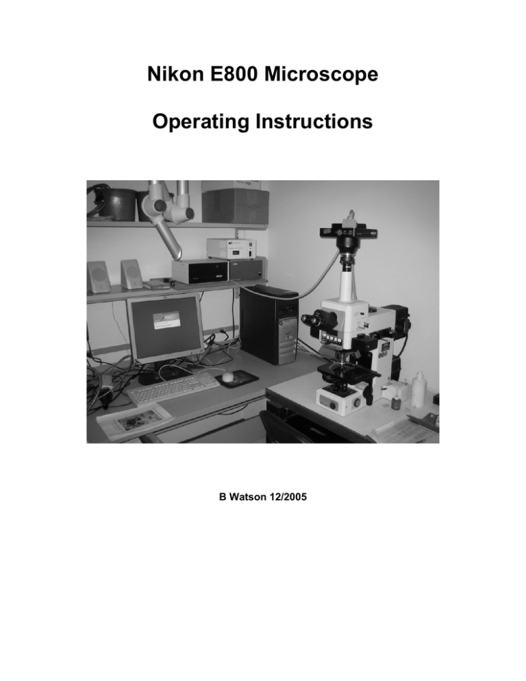
Nikon E800 Microscope Operating Instructions B Watson 12/2005 Table of contents: 1. The Nikon E800 Microscope 2. Turning the system ON and OFF 3. Selecting the light path 4. Operating in transmitted light mode 5. Adjusting the Microscope for Koehler illumination 6. Setting the microscope for DIC 7. Setting the microscope for fluorescence 8. Starting imaging software Nikon E800 Operating Instructions 1. The Nikon E800 Microscope The Nikon E800 is a fixed-stage upright microscope configured to image in transmitted light, DIC, and epifluorescence modes. The Nikon is equipped with the following objectives: 10x/0.30 20x/0.50 40x/0.75 60x/1.4 100x/1.3 PlanFluor PlanFluor PlanFluor PlanApo PlanFluor pH 1 DLL DIC M DIC M DIC H DIC H ∞/0.17 WD ∞/0.17 WD ∞/0.17 WD ∞/0.17 WD ∞/0.17 WD 16.0 2.1 0.72 0.21 0.2 Oil Oil The last two objectives are Oil immersion objectives (as noted by the black ring near the bottom). The condenser is: C-CU with 0.9 N.A. dry lens (swing-out) It contains the inserts: A(bright field) / DIC L / DIC M / DIC H / pH 1 / ø / ø DIC lens prisms are inserted above each individual objective lens. The Nikon also has a filter cube slider with the following epi filter cubes (chromatograms are available in the back of the Nikon E800 Info binder): 1. Triple DAPI/FITC/Texas Red, 96166M, C-32579 2. DAPI, 31000 810 3. WB BLUE, C35285 4. Visible (use when epi is not needed) 5. TRITC, 31002 In addition, we have the two following cubes: Triple DAPI/FITC/TRITC, 96165M FITC, 31001, C00374 These cubes can be interchanged (ask the staff) 2. Turning ON the system SPOT CAMERA 1 2 3 1 – Mercury Lamp Power Supply 2 – SPOT Camera Power Supply 3 – Microscope Power Supply MODE SWITCH 2.1 Power ON the mercury (Hg) arc lamp at the power supply (if using fluorescence). Record the time on the lamp log sheet next to the microscope to help track hours. 2.2 Power ON the microscope power supply. 2.3 Power ON the Spot Diagnostics 3CCD camera power supply (if needed.) 2.4 To turn OFF the system, turn off the power supplies in the reverse order as above. Record the time off on the mercury lamp log sheet. IMPORTANT: IF YOU ARE THE LAST USER, ESPECIALLY AFTER HOURS OR DURING WEEK-ENDS, ALWAYS REMEMBER TO POWER SYSTEM OFF WHEN DONE: 2.5 Clean any IMMERSION OIL from the objectives using lens tissue (fold one or two sheets of tissue in two, hold by the edges and gently wipe the bottom of the objective; repeat with new tissue if necessary.) 2.6 Ensure everything is off before you cover the microscope. 3. Selecting the light path. Two sliders on the right side of the eyepiece select the light path. Lower Slider (2) IN: this would only be used if the system had a second camera Lower Slider (2) OUT: Spot color 3CCD Digital Camera and eyepiece Upper Slider (1) IN: Eyepiece Upper Slider (1) OUT: Spot color 3CCD Digital Camera Slider 3: Infra-Red protection for CCD camera (leave in the engaged (IN) position). 4. Operating in transmitted light mode. 4.1 Use switch on the front base of microscope to select transmitted light (DIA). 4.2 If Hg lamp is ON, engage Hg lamp block (pull slider OUT) to block Hg lamp 4.3 Select blank filter cube (VIS or DIA-ILL) 4.4. Choose objective. Apply a SMALL drop of immersion oil to sample if using an immersion lens. Inspect objective markings and chart on the wall to make sure you do not apply immersion oil to a dry lens. TELL THE LAB STAFF IF YOU ACCIDENTLY DO. 4.5. Focus on sample. 4.6 Adjust illumination intensity with power dial on left side of microscope 4.7. Engage filters for transmitted illumination if required (e.g. neutral density to attenuate light). Push lever down to engage filter. 4.8 Remove polarizer and analyzer from the light path. (swing polarizer (1) out; pull analyzer (2) out). 4.9. Set Condenser turret to position A (for normal transmitted light) 5. Adjusting the microscope for Koehler illumination. Typically, the microscope will be properly adjusted. The only adjustments you need to do is to open the field diaphragm to just enclose the field of view for your objective, and adjust the condenser aperture. The full procedure is described below. 5.1 Stop down (close) field diaphragm by rotating dial on left side of microscope base 5.2 Focus field diaphragm by moving condenser UP or DOWN (1) 5.3 Center field diaphragm using condenser centering screws (2) 5.4. Open field diaphragm barely wider than the field of view (see Fig 4.1) 5.5 Open condenser aperture diaphragm to about 75% of the objective back aperture. You can examine the objective back aperture by removing one eyepiece and looking down the tube. As an approximation, the condenser aperture should be set to minimum for 10x objective and to max for 100x objective: 10x: setting 20x 40x 60x 100x ~2 ~5 ~7 ~9 ~9 <open-close> O|||||||||o 10 0 6. Adjusting the microscope for DIC. Typically, the microscope will be properly adjusted. Normally, you only need to select the condenser prism matching your objective, and engage the polarizer and analyzer. The whole procedure is described below. 6.1 Engage Polarizer (swing over light path; left) and Analyzer (slide IN; right) 6.2 Select position A on condenser turret (no DIC prism engaged) 6.3 Disengage objective prism by pulling prism slider OUT (without removing completely; the DIC objective prisms are the little sliders located just above each objective). Note: make sure to disengage the prism directly above the objective in use (in the image below, the prism shown belongs to an objective that is NOT in use). 6.4 Verify that field is dark. Rotate polarizer for minimum transmission (normally when set to –o-) 6.5 engage objective prism (push IN) 6.6 select matching condenser prism (H, L or M; read DIC label on objective or use Table in section 1) 6.7 for fine adjustments, rotate analyzer dial (make sure to unlock by rotating screw on top) 7. Setting the Microscope for Fluorescence. 7.1 Disengage Analyzer (1; pull OUT) Note: the polarizer is not in the epi-illumination light path, and therefore does not affect its quality. 7.2 Pull epi-illumination shutter OUT to block light (2). 7.3 select EPI setting on front base dial (will work on OFF too) 7.4 Select fluorescence filter cube by moving slider Filter positions (from left to right). Position 1: Triple DAPI/FITC/TRITC Position 2: DAPI Position 3: WB BLUE Position 4: VIS (non-epi) Position 5: TRITC (Rhodamine) Chromatograms with information on excitation, dichroic and emission wavelengths are available in the Nikon E800 Info binder. 7.5. Open fluorescence illumination shutter by pushing IN 7.6. Select the smallest convenient illumination field aperture using the epifluorescence field diaphragm (1). Center if necessary using the two centering screws (2). 7.7 Always pull shutter OUT when not imaging or viewing to minimize photobleaching of your sample. 8. Starting Imaging Software 8.1 Verify that the camera power supply is ON 8.2 Focus your image and ensure any needed filters are in place. 8.3 Login to the computer and double-click on the Spot32 icon on desktop. This will launch the photo acquisition software. 8.4 Adjust the light path for the camera: Lower Slider (1) IN/OUT: Not used at Palmer Upper Slider (2) IN: Eyepiece Upper Slider (2) OUT: Diagnostic Spot 32 3CCD camera 8.5 Initialize the camera in the program 8.6 Chose an image setup from the available list, depending on what type of settings you are using on the microscope 8.7 Start taking pictures with the snap picture icon Adjust exposure and collect Image. Use “Save as” to save the image to your local folder or the network. Note: Spot32 does not record the type of objective used. For distance measurements on your image, you need to record that information (e.g. by adding it as a separate info file). The camera is not difficult to use, however, taking advantage of its various features can be trying. There is very little documentation and the help menu is not impressive. Many users find it easiest to grab an image and then modify and filter it in Photoshop instead of trying to get exactly what they want through the camera. Please see the Instrument Tech if you have problems with the system.
