MT-029
TUTORIAL
Optical Encoders
by Walt Kester
Among the most popular position measuring sensors, optical encoders find use in relatively low
reliability and low resolution applications. An incremental optical encoder (left-hand diagram in
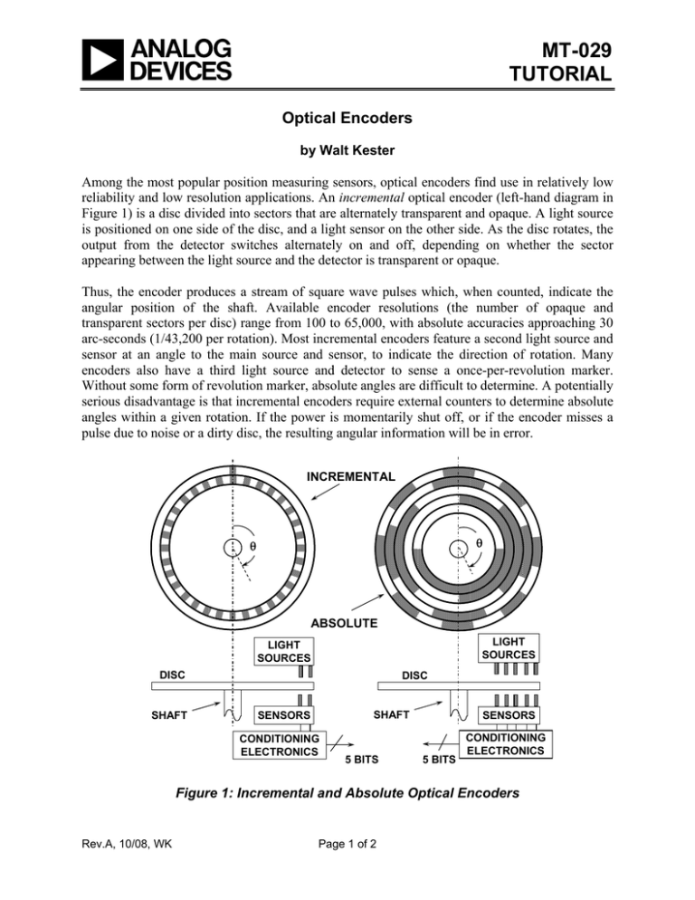
Figure 1) is a disc divided into sectors that are alternately transparent and opaque. A light source
is positioned on one side of the disc, and a light sensor on the other side. As the disc rotates, the
output from the detector switches alternately on and off, depending on whether the sector
appearing between the light source and the detector is transparent or opaque.
Thus, the encoder produces a stream of square wave pulses which, when counted, indicate the
angular position of the shaft. Available encoder resolutions (the number of opaque and
transparent sectors per disc) range from 100 to 65,000, with absolute accuracies approaching 30
arc-seconds (1/43,200 per rotation). Most incremental encoders feature a second light source and
sensor at an angle to the main source and sensor, to indicate the direction of rotation. Many
encoders also have a third light source and detector to sense a once-per-revolution marker.
Without some form of revolution marker, absolute angles are difficult to determine. A potentially
serious disadvantage is that incremental encoders require external counters to determine absolute
angles within a given rotation. If the power is momentarily shut off, or if the encoder misses a
pulse due to noise or a dirty disc, the resulting angular information will be in error.
INCREMENTAL
θ
θ
ABSOLUTE
LIGHT
SOURCES
LIGHT
SOURCES
DISC
SHAFT
DISC
SHAFT
SENSORS
CONDITIONING
ELECTRONICS
5 BITS
SENSORS
5 BITS
CONDITIONING
ELECTRONICS
Figure 1: Incremental and Absolute Optical Encoders
Rev.A, 10/08, WK
Page 1 of 2
MT-029
The absolute optical encoder (right-hand diagram in Figure 1) overcomes these disadvantages
but is more expensive. An absolute optical encoder's disc is divided up into N sectors (N = 5 for
example shown), and each sector is further divided radially along its length into opaque and
transparent sections, forming a unique N-bit digital word with a maximum count of 2N – 1. The
digital word formed radially by each sector increments in value from one sector to the next,
usually employing Gray code. Binary coding could be used, but can produce large errors if a
single bit is incorrectly interpreted by the sensors. Gray code overcomes this defect: the
maximum error produced by an error in any single bit of the Gray code is only 1 LSB after the
Gray code is converted into binary code. A set of N light sensors responds to the N-bit digital
word which corresponds to the disc's absolute angular position.
Industrial optical encoders achieve up to 16-bit resolution, with absolute accuracies that
approach the resolution (20 arc seconds). Both absolute and incremental optical encoders,
however, may suffer damage in harsh industrial environments.
Copyright 2009, Analog Devices, Inc. All rights reserved. Analog Devices assumes no responsibility for customer
product design or the use or application of customers’ products or for any infringements of patents or rights of others
which may result from Analog Devices assistance. All trademarks and logos are property of their respective holders.
Information furnished by Analog Devices applications and development tools engineers is believed to be accurate
and reliable, however no responsibility is assumed by Analog Devices regarding technical accuracy and topicality of
the content provided in Analog Devices Tutorials.
Page 2 of 2

