HCT IS Series
advertisement

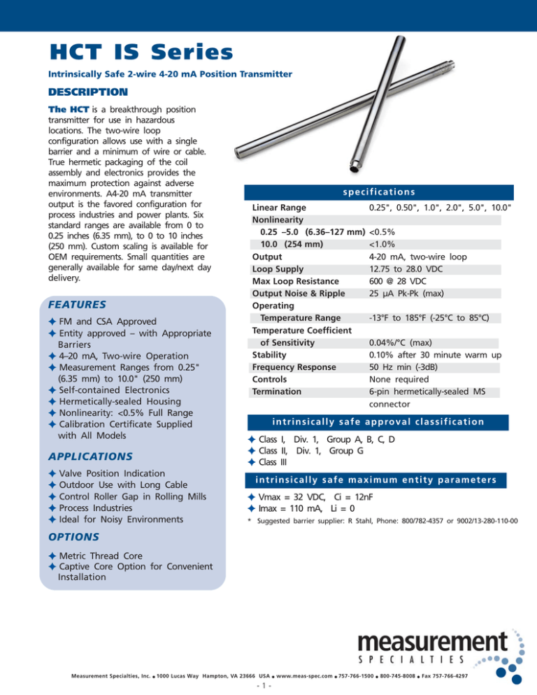
HCT IS Series Intrinsically Safe 2-wire 4-20 mA Position Transmitter DESCRIPTION The HCT is a breakthrough position transmitter for use in hazardous locations. The two-wire loop configuration allows use with a single barrier and a minimum of wire or cable. True hermetic packaging of the coil assembly and electronics provides the maximum protection against adverse environments. A4-20 mA transmitter output is the favored configuration for process industries and power plants. Six standard ranges are available from 0 to 0.25 inches (6.35 mm), to 0 to 10 inches (250 mm). Custom scaling is available for OEM requirements. Small quantities are generally available for same day/next day delivery. FEATURES FM and CSA Approved Entity approved – with Appropriate Barriers 4–20 mA, Two-wire Operation Measurement Ranges from 0.25" (6.35 mm) to 10.0" (250 mm) Self-contained Electronics Hermetically-sealed Housing Nonlinearity: <0.5% Full Range Calibration Certificate Supplied with All Models APPLICATIONS Valve Position Indication Outdoor Use with Long Cable Control Roller Gap in Rolling Mills Process Industries Ideal for Noisy Environments specifications Linear Range Nonlinearity 0.25 –5.0 (6.36–127 mm) 10.0 (254 mm) Output Loop Supply Max Loop Resistance Output Noise & Ripple Operating Temperature Range Temperature Coefficient of Sensitivity Stability Frequency Response Controls Termination 0.25", 0.50", 1.0", 2.0", 5.0", 10.0" <0.5% <1.0% 4-20 mA, two-wire loop 12.75 to 28.0 VDC 600 @ 28 VDC 25 μA Pk-Pk (max) -13°F to 185°F (-25°C to 85°C) 0.04%/°C (max) 0.10% after 30 minute warm up 50 Hz min (-3dB) None required 6-pin hermetically-sealed MS connector i n t r i n s i c a l l y s a f e a p p ro v a l c l a s s i f i c a t i o n Class I, Div. 1, Group A, B, C, D Class II, Div. 1, Group G Class III intrinsically safe maximum entity parameters Vmax = 32 VDC, Ci = 12nF Imax = 110 mA, Li = 0 * Suggested barrier supplier: R Stahl, Phone: 800/782-4357 or 9002/13-280-110-00 OPTIONS Metric Thread Core Captive Core Option for Convenient Installation Measurement Specialties, Inc. 1000 Lucas Way Hampton, VA 23666 USA -1- www.meas-spec.com 757-766-1500 800-745-8008 Fax 757-766-4297 HCT IS Series mechanical specifications HCT Series Model Number HCT 250 IS HCT 500 IS HCT 1000 IS HCT 2000 IS HCT 5000 IS HCT 10000 IS Weight Body oz 3.04 3.63 4.38 5.38 6.51 12.93 gm 86 103 124 153 185 367 oz 0.11 0.18 0.29 0.38 0.38 0.62 Core gm in 3 4.39 5 5.51 8 6.92 11 9.18 11 12.28 18 21.59 A in 1.25 1.80 3.00 3.80 3.80 6.20 mm 111.5 140.0 175.8 233.2 311.9 548.4 Dimensions B mm in 31.75 1.91 45.7 3.11 76.2 4.46 96.5 6.72 96.5 9.90 157.5 19.22 dimensions Ø 0.236 (6.0 + 0.005 + 0.127) - C mm 48.5 79.0 113.3 170.7 251.5 488.2 P in 0.96 1.52 2.23 3.36 4.91 9.56 mm 24.3 38.7 56.6 85.2 124.6 242.8 wiring Mates With MS PTO6A-10-6S Connector A Non-Hazardous Location Hazardous Location C Cable Pin E* HCT IS Series Position Transmitter 0.44 + - 0.030 (11.18 + - 0.762) P (ref only) Ø 0.750 + - 0.005 (19.1 + - 0.127) - Pin F* Power Supply Analog Input Module 2 x 4-40 UNC-2B x 0.38 (M3 x 0.5-6H x 9.7) options ordering information Number Description 006 200 + Installation must be in accordance with Intrinsically Safe control Drawing 09561512-000 * Pin A thru D no connection B Ø 0.188 + - 0.005 (4.78 + - 0.127) + Safety Barriers Specify the HCT IS model with the appropriate range followed by the desired option number(s) added together. Metric Thread Core Captive Core1 1 Available on HCT 250 IS through HCT 5000 IS models only. See below for description Ordering Example: Model NumberHCT 250 IS-206 is an HCT IS Series LVDT transmitter with a 0 to 0.250 range (HCT 250 IS), with a Metric thread core (006) and the captive core option (200). new captive core option HCT IS Model HCT HCT HCT HCT HCT HCT 250 IS 500 IS 1000 IS 2000 IS 5000 IS 10000 IS Linear Range inches mm 0 to 0.250 0 to 6.35 0 to 0.500 0 to 12.7 0 to 1.0 0 to 25.4 0 to 2.0 0 to 50.8 0 to 5.0 0 to 127.0 0 to 10.0 0 to 254.0 m a x i m u m l o o p re s i s t a n c e The HCT IS features a captive core design that greatly simplifies installation. The design utilizes a core rod and bearing assembly that is captured and guided within the LVDT providing low friction travel throughout the stroke length. The assembly incorporates two Delrin bearings on the core rod traveling through the stainless steel boreliner. A bronze bearing on the front end utilizes a self-aligning feature to accommodate lateral LVDT movement during operation. The core rod and bearing assembly are field replaceable. Measurement Specialties, Inc. 1000 Lucas Way Hampton, VA 23666 USA -2- www.meas-spec.com 757-766-1500 800-745-8008 Fax 757-766-4297 HCT-IS_0107


