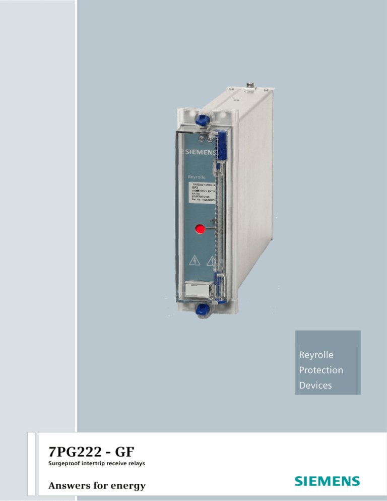
Reyrolle
Protection
Devices
7PG222 - GF
Surgeproof intertrip receive relays
Answers for energy
Siemens Protection Devices Limited
2
7PG222 – GF
Surgeproof intertrip receive relays
Application
Under fault conditions an interconnected power system may
feed fault-current from more than one source, and in order to
isolate the fault it becomes necessary to initiate the tripping
of remote circuit breakers.
The above requirement is particularly important when protecting feeder-transformers connected to the system without
circuit breakers. In the event of a transformer fault, tripping of
the local low voltage circuit breaker will not remove the fault
from the system and it becomes essential to trip the remote
high voltage circuit breaker. Intertripping can use various
information links however, type GF relays are for use with
pilot wires.
Description
Type GF relays are designed to meet the demand for a simple
surge-proof intertrip receive relay.
Experience has shown that although longitudinal voltages
can be of the order of 5kV, transverse voltages across the
pilot cores are of much lower magnitude. It follows that
although it is necessary to have a high insulation level to
earth.
It may not always be necessary to employ a relay with full
surgeproof capability such as the type BD. Type GF relays are
designed to cater for less onerous conditions.
GF relays comprise an attached armature element delayed
on pick-up and with non-linear shunt resistor and a series
resistor. They are surge proof up to 500V rms 50Hz (steady
state or switched).
GF relays are rated for 60V d.c., when required to operate at
higher supply voltages an external dropper resistor is supplied,
Siemens Protection Devices Limited
Complete reliability of the intertrip signal in the presence of
interference is of the utmost importance particularly during
internal fault conditions when this interference may be severe. Simple systems using d.c. relays may be adequate for
pilot wire lengths of up to 2km, however it should be noted
that receive relays must not be unduly sensitive to the capacitive energy stored in the pilot wires. A d.c. relay system may
also be used for longer lengths of pilot wire provided that
precautions are taken to avoid spurious operation due to either induced voltage or to differences in earth potential at the
send and receive ends.
The effects of induced voltage are most significant under
earth fault conditions when both transverse and longitudinal
voltages appear across the conductors of the pilot cable when
fault current returns through the earth path and the earth
wire. The degree of induction depends upon earth resistivity,
the disposition of auxiliary conductors relative to primary
conductors, the presence of the earth wire and the screening
effects present in both primary and auxiliary conductors.
GF2
GF3
15kV
15kV
2kV
5kV
5kV
5kV
Contact arrangement
3 NO
2 NO + 1 NC
Yes
Yes
Yes
Yes
Flag
No
Yes
Insulation level:
coil to contacts
coil to frame
contacts to frame
3
Technical information
Ratings;
60V d.c. or 125V d.c. or 220V d.c.
(125V and 220V with external dropper resistor)
Burden (Watts)
60V rating 8W 125V rating 14.6W. 220V rating 29W.
Contact Arrangement
GF2 - 3 normally open or 2 normally open and 1 normally
closed self reset.
GF3 - 3 normally open or 2 normally open and 1 normally
closed self reset.
Operation (60V rating)
Pick-up (min)
37%
Drop-off (max)
7%
Timing (60V rating)
Operating 60V (100%)
45mS
Operate 48V (80%)
50mS
Drop-off 60mS approximately
Surge Proof Up to 500V
INSULATION (a.c. volts r.m.s.)
Coil Circuit to contacts:
15kV (GF2) and 5kV (GF3)
Coil circuits to frame:
15kV (GF2) and 5kV (GF3)
Contacts to frame:
2kV (GF2) and 5kV (GF3)
Indication
Type GF3 is fitted with a hand reset flag.
Siemens Protection Devices Limited
4
Contact Rating
Making and carrying a maximum of 1500V A a.c. or 1500W
d.c. within the undermentioned limits:
Voltage:
660V
Current:
3A continuously, 8A for 3 seconds
or 16A for 1 second.
300VA a.c. or 75W d.c. (Inductive)
within the limits of 250V and 5A.
Breaking:
Case Dimensions
GF2
Size 1V Vedette flush mounting.
GF3
Size 2/3V or 1V Vedette flush or
surface mounting, or E2 Epsilon case.
External dropper resistors
These are supplied for back of panel mounting.
For GF2 relays resistors are in a box 165mm wide x 397mm
high x 152mm projection, insulated to a level of 15kV.
For GF3 relays two resistors are supplied each 43mm wide x
136mm high x 105mm projecting. These should be
mounted sufficiently clear of all other equipment so as to
maintain a 5kV insulation level.
Siemens Protection Devices Limited
5
Ordering Information - 7PG222 – GF
Product description
Variants
GF
7 P G 2 2
Intertrip receive relay.
Relay type
GF - Intertrip receive
Model type
GF2 - Intertrip receive
GF3 - Intertrip receive
Type of flag
No flag
Hand reset flag
Contact arrangement – NO
2 NO
3 NO
Contact arrangement NC
0 NC
1 NC
Number of contacts
Three
Contact type
NO (Standard) / NC (Standard)
Insulation level
5kV
15kV
Housing size
Case size E2 (4U high)
Case size C1 Vedette
Rating
60V DC
125V DC 1)
240V DC 1)
1)
Order No.
□□ - □□□□□ - □□□ 0
▲ ▲
▲ ▲ ▲ ▲ ▲
▲ ▲ ▲
| | | | | | | | | |
| | | | | | | | | |
| | | | | | | | | |
2 |
| | | | | | | |
| | | | | | | | |
| | | | | | | | |
2
0 | | | |
2 U |
3
1 | | | |
1 A |
| | | | | | | |
| | | | | | | |
0 | | | |
| | |
1 | | | |
| | |
| | | | | | |
| | | | | | |
C B | |
| | |
D A | |
| | |
| | | | | |
| | | | | |
A | |
| | |
B | |
| | |
| | | | |
| | | | |
3 |
| | |
| | | |
| | | |
0
| | |
| | |
| | |
1 | |
2 | |
| |
| |
A |
U |
|
|
D
E
F
Relay rated at 60V dc, for higher ratings external resistors are required
GF2 - 125V dc, includes resistor box assembly VCE:2750H30010; 240V dc, includes resistor box assembly VCE:2750H30020
GF3 - 125V dc, includes two resistors VCE:2101H10102; 240V dc, includes two resistors VCE:2101H10252, also includes perspex cover VCE:410A23995 (1 per resistor)
Siemens Protection Devices Limited
6
Siemens Protection Devices Limited
7
Published by and copyright © 2010:
Siemens AG
Energy Sector
Freyeslebenstrasse 1
91058 Erlangen, Germany
Siemens Protection Devices Limited
P.O. Box 8
North Farm Road
Hebburn
Tyne & Wear
NE31 1TZ
United Kingdom
Phone: +44 (0)191 401 7901
Fax:
+44 (0)191 401 5575
www.siemens.com/energy
For more information, please contact our
Customer Support Center.
Phone: +49 180/524 70 00
Fax:
+49 180/524 24 71(Charges depending on provider)
E-mail: support.energy@siemens.com
Power Distribution Division Order No. E53000-K7076-C23-1
Printed in Fürth
Printed on elementary chlorine-free bleached paper.
All rights reserved.
Trademarks mentioned in this document are the property of Siemens AG, its affiliates, or their respective owners.
Subject to change without prior notice.
The information in this document contains general
descriptions of the technical options available, which
may not apply in all cases. The required technical
options should therefore be specified in the contract.
www. siemens.com/energy
Siemens Protection Devices Limited
8


