RidgeLine Series Installation Instructions - Dual-Lite
advertisement
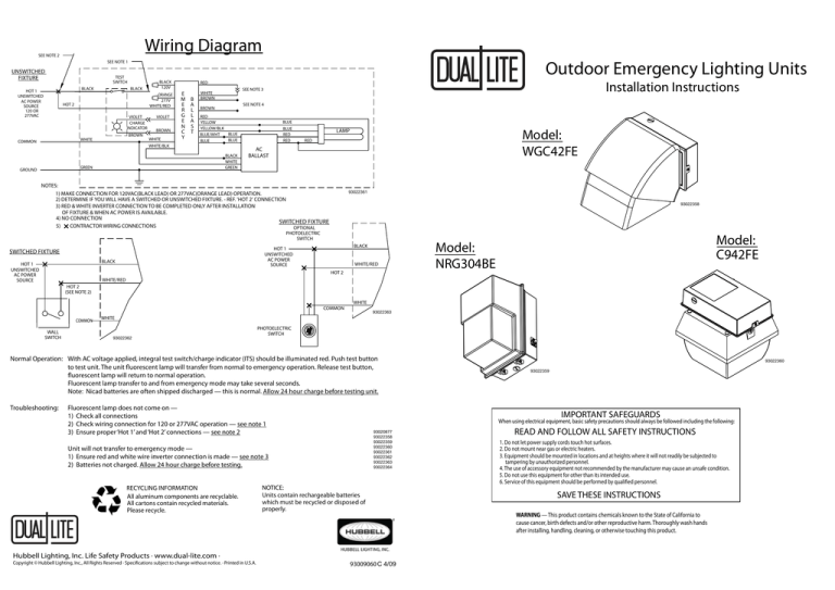
Wiring Diagram SEE NOTE 2 Outdoor Emergency Lighting Units SEE NOTE 1 UNSWITCHED FIXTURE TEST SWITCH BLACK BLACK HOT 1 UNSWITCHED AC POWER SOURCE 120 OR 277VAC ORANGE 277V WHITE/RED HOT 2 VIOLET CHARGE INDICATOR BROWN WHITE COMMON BLACK 120V VIOLET BROWN WHITE WHITE/BLK E M B E A R L G L E A N S C T Y SEE NOTE 3 WHITE BROWN SEE NOTE 4 BROWN RED YELLOW YELLOW/BLK BLUE BLUE/WHT BLUE BLUE BLACK WHITE GREEN GREEN GROUND Installation Instructions RED BLUE BLUE RED RED Model: WGC42FE LAMP RED AC BALLAST NOTES: 1) MAKE CONNECTION FOR 120VAC(BLACK LEAD) OR 277VAC(ORANGE LEAD) OPERATION. 2) DETERMINE IF YOU WILL HAVE A SWITCHED OR UNSWITCHED FIXTURE. - REF. 'HOT 2' CONNECTION 3) RED & WHITE INVERTER CONNECTION TO BE COMPLETED ONLY AFTER INSTALLATION OF FIXTURE & WHEN AC POWER IS AVAILABLE. 4) NO CONNECTION SWITCHED FIXTURE 5) CONTRACTOR WIRING CONNECTIONS OPTIONAL 93022361 93022358 PHOTOELECTRIC SWITCH BLACK HOT 1 UNSWITCHED AC POWER SOURCE BLACK HOT 1 UNSWITCHED AC POWER SOURCE SWITCHED FIXTURE WHITE/RED HOT 2 Model: C942FE Model: NRG304BE WHITE/RED HOT 2 (SEE NOTE 2) COMMON COMMON WALL SWITCH WHITE 93022363 WHITE 93022362 PHOTOELECTRIC SWITCH Normal Operation: With AC voltage applied, integral test switch/charge indicator (ITS) should be illuminated red. Push test button to test unit. The unit fluorescent lamp will transfer from normal to emergency operation. Release test button, fluorescent lamp will return to normal operation. Fluorescent lamp transfer to and from emergency mode may take several seconds. Note: Nicad batteries are often shipped discharged — this is normal. Allow 24 hour charge before testing unit. Troubleshooting: Fluorescent lamp does not come on — 1) Check all connections 2) Check wiring connection for 120 or 277VAC operation — see note 1 3) Ensure proper ‘Hot 1’ and ‘Hot 2’ connections — see note 2 IMPORTANT SAFEGUARDS When using electrical equipment, basic safety precautions should always be followed including the following: 93020877 93022358 93022359 93022360 93022361 93022362 93022363 93022364 Unit will not transfer to emergency mode — 1) Ensure red and white wire inverter connection is made — see note 3 2) Batteries not charged. Allow 24 hour charge before testing. RECYCLING INFORMATION All aluminum components are recyclable. All cartons contain recycled materials. Please recycle. NOTICE: Units contain rechargeable batteries which must be recycled or disposed of properly. Hubbell Lighting, Inc. Life Safety Products · www.dual-lite.com · Copyright © Hubbell Lighting, Inc., All Rights Reserved · Specifications subject to change without notice. · Printed in U.S.A. 93022360 93022359 93009060 C A 11/08 4/09 READ AND FOLLOW ALL SAFETY INSTRUCTIONS 1. Do not let power supply cords touch hot surfaces. 2. Do not mount near gas or electric heaters. 3. Equipment should be mounted in locations and at heights where it will not readily be subjected to tampering by unauthorized personnel. 4. The use of accessory equipment not recommended by the manufacturer may cause an unsafe condition. 5. Do not use this equipment for other than its intended use. 6. Service of this equipment should be performed by qualified personnel. SAVE THESE INSTRUCTIONS WARNING — This product contains chemicals known to the State of California to cause cancer, birth defects and/or other reproductive harm. Thoroughly wash hands after installing, handling, cleaning, or otherwise touching this product. Installation Instructions BLACK, HOT 1 120 OR 277VAC UNSWITCHED * SEE NOTE 1 UNDER WIRING DIAGRAM MUST BE CONNECTED TO EITHER 120 OR 277VAC OF EMERGENCY BALLAST UNS WIT CHE D WHITE/RED , HOT 2 (THIS LEAD MUST BE CONNECTED TO INCOMING POWER, EITHER SWITCHED OR UNSWITCHED) SEE WIRING DIAGRAM - NOTE 2 12 27 0 OR 7V AC BALLAST HSG SWITCH ED WHITE COMMON MAKE CONNECTION FOR CHARGE INDICATOR EMERGENCY BALLAST GREEN GROUND * BLACK 120V SEE NOTE 1 UNDER WIRING DIAGRAM 93022364 1) REMOVE 7/8" DIA. K.O. FROM HSG IF MOUNTING TO ELECTRICAL BOX OR REMOVE 1/2-14NPT PIPE PLUG IF USING CONDUIT. 2) REMOVE APPROPRIATE HSG K.O's FOR ELECTRICAL BOX SCREWS. 3) FEED BUILDING WIRES THRU GASKET AND BALLAST HSG & SECURE HSG USING SCREWS SUPPLIED WITH ELECTRICAL BOX. 4) SEE WIRING DIAGRAM FOR REQUIRED CONNECTIONS. * ORANGE 277V SEE NOTE 1 UNDER WIRING DIAGRAM TEST SWITCH/CHARGE INDICATOR SEE NOTE 3 UNDER WIRING DIAGRAM 93020877 BALLAST COVER LIGHTING FIXTURE MODELS: WGC42FE C942FE NRG304BE

