LED Indicators DIP-switch Rear Panel Connections
advertisement
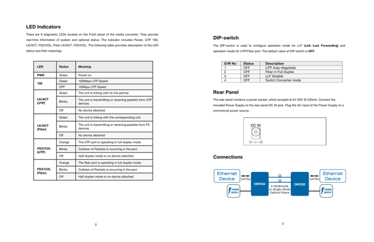
LED Indicators There are 6 diagnostic LEDs located on the Front panel of the media converter. They provide real-time information of system and optional status. The indicator includes Power, UTP 100, DIP-switch LK/ACT, FDX/COL, Fiber LK/ACT, FDX/COL. The following table provides description of the LED The DIP-switch is used to configure operation mode for LLF (Link Lost Forwarding) and status and their meanings. operation mode for UTP/Fiber port. The default value of DIP switch is OFF. S/W No 1 2 3 4 Status OFF OFF OFF OFF Description UTP Auto-Negotiate Fiber in Full Duplex LLF Disable Switch Converter mode LED Status Meaning PWR Green Power on Green 100Mbps UTP Speed OFF 10Mbps UTP Speed Green The unit is linking with its link partner. Blinks The unit is transmitting or receiving packets from UTP devices. The rear panel contains a power socket, which accepts 8–24 VDC @ 220mA. Connect the Off No device attached commercial power source. Green The unit is linking with the corresponding unit. Blinks The unit is transmitting or receiving packets from FX devices. Off No device attached Orange The UTP port is operating in full-duplex mode. Blinks Collision of Packets is occurring in the port. Off Half-duplex mode or no device attached Orange The fiber port is operating in full-duplex mode. Blinks Collision of Packets is occurring in the port. Off Half-duplex mode or no device attached 100 LK/ACT (UTP) LK/ACT (Fiber) FDX/COL (UTP) FDX/COL (Fiber) Rear Panel included Power Supply to the rear panel DC IN jack. Plug the AC input of the Power Supply to a DC IN Connections Ethernet Device CAT5e CAT5e CWFE2SC POWER SUPPLY 2 2 Multimode or Single Mode Optical Fibers 3 Ethernet Device CWFE2SC POWER SUPPLY Full Documentation This Quick Start Guide is only partial installation information, intended for users who need only the default settings for this product model. To change settings or for more detailed explanation of features and settings, please consult the full Installation Manual, provided on disk with the product or available at www.comnet.net. ComNet Customer Service QUICK START GUIDE Customer Care is ComNet Technology’s global service center, where our professional staff are ready to answer your questions at any time. Email address of ComNet Global Service Center: CWFE2SC(M)(S)2 customercare@ComNet.net COMMERCIAL GRADE 10/100 MBPS ETHERNET 2 PORT MEDIA CONVERTER 1 CHANNEL: ELECTRICAL OPTICAL The ComWorx™ VL CWFE2SC(M)(S)2 Ethernet 2 port media converters are designed to transmit and receive 10/100 Mbps data over multimode or single mode optical fiber. The electrical interface will Auto-Negotiate to a 10 Mbps, or 100 Mbps Ethernet rate without any adjustments. The optical interface operates at a 100 Mbps Ethernet rate. These media converters are commercial grade for light industrial use. Communication Networks World Headquarters ComNet Europe Ltd 3 Corporate Drive 8 Turnberry Park Road Danbury, CT 06810 USA Gildersome, Morley The Front Panel of the ComNet CWFE2SC(M)(S)2 consists of one RJ45 Port (Auto MDI/MDIX), 6 T 203 796-5300 Leeds, LS27 7LE, UK LED Indicators (UTP 100, LK/ACT, FDX/COL, Fiber LK/ACT, FDX/COL and PWR) and one fiber F 203 796-5303 T +44 (0)113 307 6400 100Base-FX Port. 888 678-9427 Tech Support F +44 (0)113 253 7462 info@ComNet.net info-europe@ComNet.net © 2010 Communication Networks. All rights reserved. Front Panel Fast Fiber Converter Module-- SC 2 1 4 3 The COMNET logo is a registered trademark of Communication Networks Corporation. Additional Company and product names may be trademarks or registered trademarks of the individual companies and are respectfully acknowledged and do not imply endorsement. 4 1
