Assembly Drawing Rules & Features: Engineering Lesson
advertisement
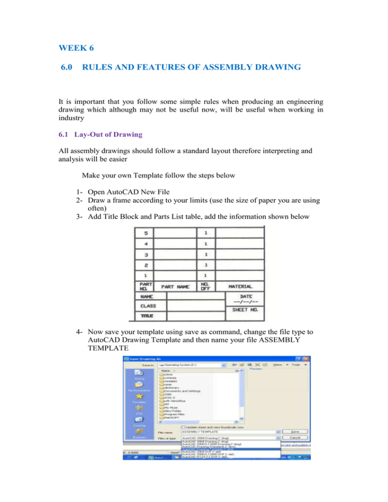
WEEK 6 6.0 RULES AND FEATURES OF ASSEMBLY DRAWING It is important that you follow some simple rules when producing an engineering drawing which although may not be useful now, will be useful when working in industry 6.1 Lay-Out of Drawing All assembly drawings should follow a standard layout therefore interpreting and analysis will be easier Make your own Template follow the steps below 1- Open AutoCAD New File 2- Draw a frame according to your limits (use the size of paper you are using often) 3- Add Title Block and Parts List table, add the information shown below 4- Now save your template using save as command, change the file type to AutoCAD Drawing Template and then name your file ASSEMBLY TEMPLATE 6.2 Parts list Each part is given a unique number, indicated on the drawing by a circle with the number in it and a leader line pointing to the part. The leader line terminates in an arrow if the line touches the edge of the component.. A table of parts should be added to the drawing to identify each part, an example of a parts list is shown below: PART NO. PART NAME NO. OFF MATERIAL 6.3 Dimensions Detailed dimensions required for manufacture are excluded from assembly drawings. But overall dimensions of the assembled object are usually indicated 6.4 Task 3 Fig (35) illustrates the details of V BLOCK ASSEMBLY, using scale 1:1 and first angle of projection draw the following: 1- An assembled sectional Front View 2- Add Title block and parts list 3- Add 8 main dimensions Fig 6

