PCI Bus Target Interface Megafunction
Solution Brief 25
Target Application:
Buses & Interfaces
Family:
FLEX 10K & FLEX 8000
Vendor:
PLD Applications
14 rue Soleillet
Paris 75020
France
Tel. (33) 01-40-33-79-98
Fax. (33) 01-43-58-14-15
plda@worldnet.fr
http://www.plda.com
May 1997, ver. 1
Features
■
■
■
■
■
■
Optimized for the Altera® FLEX® 10K and FLEX 8000 device architectures
Fully compliant with peripheral component interconnect Special Interest Group
(PCI-SIG) PCI Local Bus Specification, Rev. 2.1
Fully synchronous design
Fully hardware tested
Supports full-speed burst support up to 132 Mbytes/second
Provides zero-wait state data transfer rate
General Description
The PCI bus target interface megafunction is a 32-bit PCI bus interface that is used for
high-speed data transfers and real-time computing applications such as fast dataintensive projects and migration of ISA-based designs to PCI bus designs. Figure 1
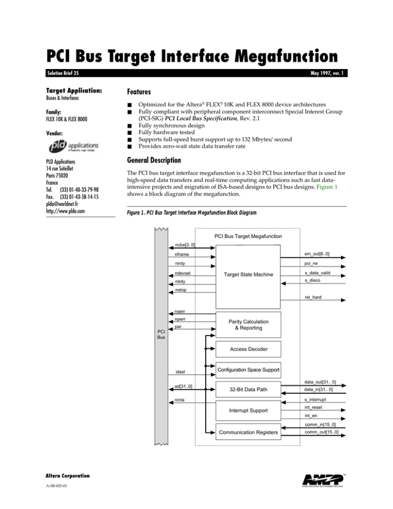
shows a block diagram of the megafunction.
Figure 1. PCI Bus Target Interface Megafunction Block Diagram
PCI Bus Target Megafunction
ncbe[3..0]
nframe
sm_out[6..0]
nirdy
pci_rw
ndevsel
Target State Machine
s_data_valid
s_disco
ntrdy
nstop
rst_hard
nserr
nperr
par
PCI
Bus
Parity Calculation
& Reporting
Access Decoder
idsel
ad[31..0]
Configuration Space Support
data_out[31.. 0]
32-Bit Data Path
data_in[31.. 0]
s_interrupt
ninta
Interrupt Support
int_reset
int_en
comm_in[15..0]
Communication Registers
comm_out[15..0]
Altera Corporation
A-SB-025-01
SM
ALTERA MEGAFUNCTION PARTNERS PROGRAM
SB 25: PCI Bus Target Interface Megafunction
Functional Description
The PCI bus target interface megafunction provides a simple and flexible interface
between a PCI bus and a user-developed back-end application. The megafunction
maintains high performance and accuracy through full parity calculation and
reporting. PCI bus handling is implemented with full support for disconnect and retry
events; the megafunction handles one interrupt.
Performance
The PCI bus target interface megafunction operates at 33 MHz. Table 1 provides the
typical utilization results for the megafunction.
Table 1. Typical Utilization Results for the PCI Bus Target Interface Megafunction
Implementation
32-bit PCI bus target
32-bit PCI bus target with
internal SRAM
Target Device
Clock (fMAX)
EABs
Logic Cells
% of Logic
Cells Used
EPF10K10-3
33 MHz
0/3
340 / 576
60%
EPF10K20-3
33 MHz
0/6
340 / 1152
30%
EPF10K30-3
33 MHz
0/6
340 / 1728
20%
EPF10K40-3
33 MHz
0/8
340 / 2304
15%
EPF10K10-3
33 MHz
3/3
340 / 576
80%
EPF10K20-3
33 MHz
4/6
450 / 1152
40%
EPF10K30-3
33 MHz
4/6
450 / 1728
25%
EPF10K40-3
33 MHz
4/8
450 / 2304
20%
Customization
The PCI bus target interface megafunction is fully parameterizable, allowing the
designer to customize the memory space location and size (between 16 bytes and
64 Mbytes), and the device, vendor, class code, and revision ID registers.
Hardware Testing
The PCI bus target interface megafunction has been developed and tested using the
PCI_GEN02 PCI bus evaluation board (available from PLD Applications). The
PCI_GEN02 contains an EPF10K10 device that implements the megafunction. The
megafunction uses only 60% of the EPF10K10 device, the remaining logic and EAB
resources are available for user-defined custom logic. Figure 2 shows a block diagram
of the PCI_GEN02 PCI bus evaluation board.
Altera Corporation
2
SB 25: PCI Bus Target Interface Megafunction
Figure 2. Block Diagram of the PCI_GEN02 PCI Bus Evaluation Board
PCI_GEN02 Hardware Prototyping Evaluation Board
EPC1
BitBlaster/ByteBlaster
Download Cable
Connector
External
Power
Connector
Component
Prototyping
Area
EPF10K10
50-Pin External I/0
Connect or (Optional)
PCI Bus
Three 50-Pin I/O Connectors
The EPF10K10 device can be configured using an EPC1ª Configuration EPROM, a
BitBlasterª download cable, or a ByteBlasterª download cable. These options allow
the designer to choose between a variety of configuration techniques. Three 50-pin
headers are provided for a daughter card, and a 50-pin off-card connector is supported
by the PCI_GEN02 solder mask.
PCI bus target applications can also be developed and tested using the PCI_GEN01 PCI
bus evaluation board. The PCI_GEN01 is used to implement custom hardware on the
PCI bus. The PCI_GEN01 contains an EPM7256S device that implements the PCI target
interface and an EPF10K50 device that is used for user-defined custom logic. The
EPF10K50 device can be configured using an EPC1 Configuration EPROM or via the
PCI target interface. Figure 3 shows a block diagram of the PCI_GEN01 PCI bus
evaluation board.
Figure 3. Block Diagram of the PCI_GEN01 PCI Bus Evaluation Board
PCI_GEN01 Hardware Prototyping Evaluation Board
EPC1
EPM7256S
128K SRAM
(Shared)
EPF10K50
Status LEDs
64K SRAM
(PCI Bus Signal
Sampling)
32-Pin External
I/0 Interface
PCI Bus
Altera Corporation
3
SB 25: PCI Bus Target Interface Megafunction
The EPF10K50 device provides significant logic resources for implementing and
evaluating hardware on the PCI bus. The EPM7256S and EPF10K50 devices share a
common 128-Kbyte SRAM space. The EPM7256S device controls a separate 64-Kbyte
SRAM buffer that captures PCI bus control signals and provides a signal analyzer for
the PCI bus. The EPF10K50 device drives the four status LEDs, and it is connected to
an external 32-pin I/O interface.
Reference
PCI Special Interest Group. PCI Local Bus Specification. Rev.2.1 Hillsboro, Oregon:
PCI Special Interest Group, 1995.
®
2610 Orchard Parkway
San Jose, CA 95134-2020
(408) 544-7000
http://www.altera.com
4
Copyright 1997 Altera Corporation. Altera, AHDL, AMPP, BitBlaster, ByteBlaster, EPC1, FLEX, FLEX 10K, FLEX 8000, EPF10K50, EPF10K30,
EPM7256, and EPM7256S are trademarks and/or service marks of Altera Corporation in the United States and other countries. Other brands
or products are trademarks of their respective holders. The specifications contained herein are subject to change without notice. Altera assumes
no responsibility or liability arising out of the application or use of any information, product, or service described herein except as expressly
agreed to in writing by Altera Corporation. Altera customers are advised to obtain the latest version of device specifications before relying on
any published information and before placing orders for products or services. All rights reserved.
Altera Corporation


