From:MAICS-99 Proceedings. Copyright © 1999, AAAI (www.aaai.org). All rights reserved.
The Argus Project:
Investigation
A Binocular Stereovision
Head for the
of Distributed Visual Attention
J. Oliver Ross and Douglas S. Blank
Department of Computer Science and Computer Engineering
University of Arkansas
Fayetteville, AR72701
{j oross,dbl~n~}~comp,
uark.edu
Abstract
A 5 degree-of-freedom binocular stereovision head,
called Argus, is described which has been designed for
independentcameracontrol (other than that of occular
vergence). The system was inspired by both the abilities and behaviors of the chameleonvisual system. A
unique control architecture is described whichenables
hierarchical learning of visual behaviors, including independentsearch for an object of interest coupled with
dual-cameraobject fixation upon successful completion
of the search.
Hardware
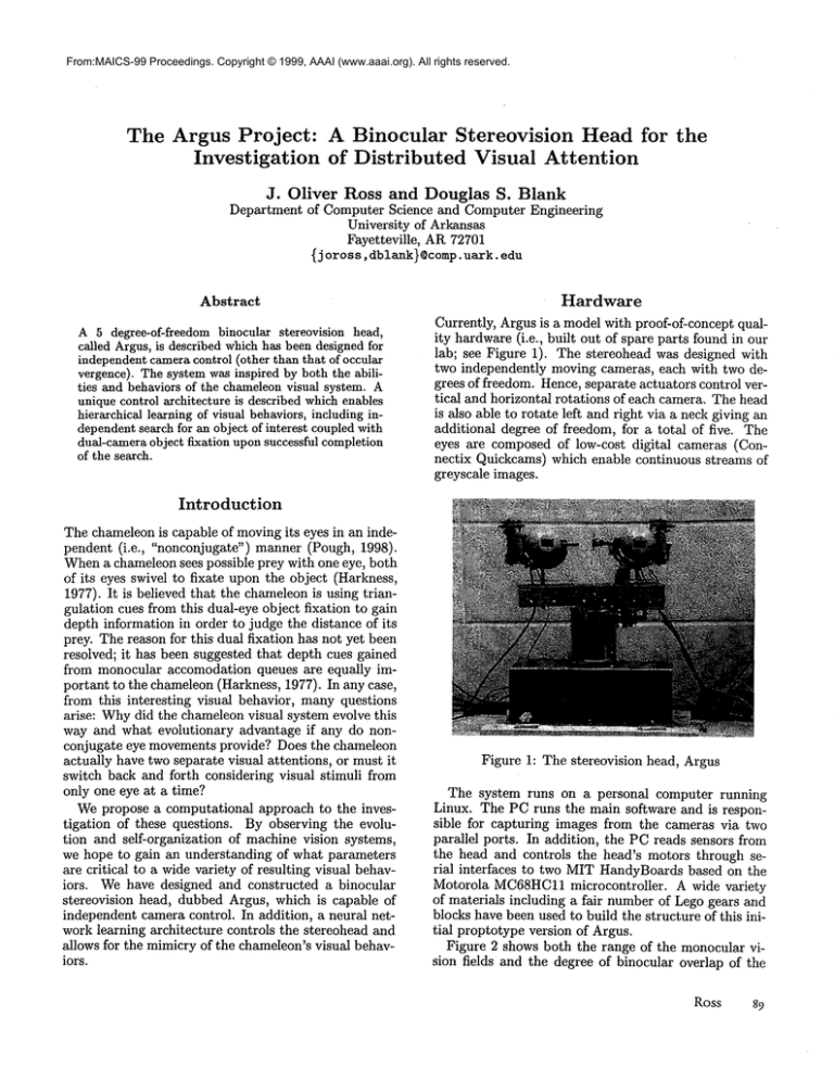
Currently, Argus is a model with proof-of-concept quality hardware (i.e., built out of spare parts found in our
lab; see Figure 1). The stereohead was designed with
two independently moving cameras, each with two degrees of freedom. Hence, separate actuators control vertical and horizontal rotations of each camera. The head
is also able to rotate left and right via a neck giving an
additional degree of freedom, for a total of five. The
eyes are composed of low-cost digital cameras (Connectix Quickcams) which enable continuous streams of
greyscale images.
Introduction
The chameleon is capable of moving its eyes in an independent (i.e., "nonconjugate") manner (Pough, 1998).
Whena chameleon sees possible prey with one eye, both
of its eyes swivel to fixate upon the object (Harkness,
1977). It is believed that the chameleonis using triangulation cues from this dual-eye object fixation to gain
depth information in order to judge the distance of its
prey. The reason for this dual fixation has not yet been
resolved; it has been suggested that depth cues gained
from monocular accomodation queues are equally important to the chameleon (Harkness, 1977). In any case,
from this interesting visual behavior, many questions
arise: Whydid the chameleon visual system evolve this
way and what evolutionary advantage if any do nonconjugate eye movements provide? Does the chameleon
actually have two separate visual attentions, or must it
switch back and forth considering visual stimuli from
only one eye at a time?
Wepropose a computational approach to the investigation of these questions. By observing the evolution and self-organization of machine vision systems,
we hope to gain an understanding of what parameters
are critical to a wide variety of resulting visual behaviors. Wehave designed and constructed a binocular
stereovision head, dubbed Argus, which is capable of
independent camera control. In addition, a neural network learning architecture controls the stereohead and
allows for the mimicry of the chameleon’s visual behaviors.
Figure 1: The stereovision
head, Argus
The system runs on a personal computer running
Linux. The PC runs the main software and is responsible for capturing images from the cameras via two
parallel ports. In addition, the PC reads sensors from
the head and controls the head’s motors through serial interfaces to two MIT HandyBoards based on the
Motorola MC68HC11
microcontroller.
A wide variety
of materials including a fair number of Lego gears and
blocks have been used to build the structure of this initial proptotype version of Argus.
Figure 2 shows both the range of the monocular vision fields and the degree of binocular overlap of the
Ross
89
I
I
°
180
18~,"
Ii
i
i
ii
I
I
I
Computational Architecture
Image Processing Module
i
Figure 2: Stereohead geometry
stereohead.
Hierarchical
Learning
Model
Weare primarily interested in designing systems in
which high-level behavior emerges from low level computational primitives due to interaction with the realworld environment. Wemust therefore specify knowledge and relationships to be learned at each hierarchical level in such a manner that knowledge learned at
lower levels may be exploited by learning subsystems
at higher levels. Once knowledgeto be learned at each
level has been specified, choice of learning algorithms
for execution of a particular task then becomes obvious.
At the lowest level, each eye must learn to locate and
fixate upon objects of interest. The camera reaches its
goal state whena target object is centered in the camera
image. If the object is in motion, the camera should
attempt to maintain fixation by tracking the object.
At the second level, each eye must learn its vestibuloocular response (VOR). VORis defined as compensatory motion of the eye due to movementof the head.
Consider the scenario in which one eye, here referred
to as the primary eye, has located and is fixating upon
an object of interest. One of the system goals at this
point is for the secondary camera to also locate and
fixate upon the object. At this point, if the head is
allowed to turn in addition to the rotational motion of
the secondary camera, the primary camera must compensate for the rotational motion of the head in order
to maintain fixation upon the object.
At the third level, the system must learn to center
its head such that it is pointed directly toward the object. What information may be exploited to obtain this
goal? One answer is for the system to seek to minimize
differences between the object’s size in each camera’s
image. If the size difference of the object in the two images is minimized, the binocular stereo disparity will in
turn be minimized. This is an advantage when trying to
extract stereo and depth information from the images,
90
MAICS-99
the primary function of the system. The result is that
the system minimizes the difference of the distances of
its two cameras to the object, thus centering the head
facing toward the object.
Wehave described a set of energy functions which
our system should minimize in order to reach a final
positional steady-state. Next, we discuss an underlying computational architecture which through learning
over time, enables a fluidity of motion to result such
that the system appears to be exibiting a reflex action
as opposed to executing a sequential series of separate
motions.
A minimalist image processing module (IPM) is necessary in order for Argus to recognize an object at different distances. First, an image is created of the target object. The image processing module then creates
a regular image pyramid, or sequence of images of decreasing resolution from the base image (Bischof, 1995).
These images are then used as templates enabling the
object to be located at different distances. For this task,
a standard correlation algorithm is used to compare a
portion of an image captured from a camera to each of
the image pyramid templates.
Reinforcement
Neural Network Description
A new neural network architecture,
the reinforcement
neural network (RNN), has been designed for use in the
Argus system. The RNNis similar to a Kohonen SelfOrganizing Map (Kohonen, 1990) except that instead
of creating randomspatial patterns as outputs, the network receives both positive and negative reinforcement
signals which force the creation of specific spatial patterns corresponding to predefined motor commandsfor
position and velocity control.
speed outputs
position outputs
o.Q-.... Q .....
.....
state inputs
Figure 3: Reinforcement Neural Network topology
The RNNconsists of fully connected input and output layers. The output layer is divided into two banks,
one controlling the speed commandand the other controlling the servo positioning command.Weight matrices Wsand Wpconnect the input layer to the respective
output layer banks. The weight matrices are initialized
with small random values. In this winner-take-all network, the outputs of each bank, Y8 specifying actuator
speed and yp specifying actuator servo position are the
neurons in each bank with the highest activation, defined to be the weighted sum of the inputs:
n
Ys = E ws,ili
(1)
i----1
where Ws = {ws,i}, Wp-- {Wp,i) are the weight matrices, and I represents the vector of inputs.
Reinforcement
Signal
Module
The reinforcement signals are used to modulate the
weight matrices in such a way that the network selforganizes to find both the proper servo motor position and speed control commandsfor each of the input state vectors. These reinforcement signals are generated based on the output of the image processing
system. Hence, the target object must be found by
at least one camera before any reinforcement may be
given. Whenthe target object is found, the reinforcement signal is based upon how close that camera is to
achieving its goal state. The camerais in its goal state
when the object is centered in the image. The position
reinforcement signal is a function of the Euclidean distance, G(t) of the object from the center of the image.
The reinforcement signal module (RSM)receives the
RNN’sspeed and position outputs and the motor position as well as G(t) from the Image Processing Module
as inputs and generates speed and position reinforcement signals as outputs. As the motor is turning to
the specified position, the reinforcement signal module
collects a series of G(t) values from the IPM. It also receives an acknowledgement when the motor has reached
its position as specified by the network. From the time
the network issues the servo control commandto the
time of its completion, if at any time G(t) is less than
a user specified error value, 5 then at that time, t~ the
camera is defined to be in its goal position. In the case
that the camera actuator overshot the goal state, the
time of acknowledgement, tack is greater than t~. In
this case, a reinforcement signal should be generated
which modulates the weight matrix such that the motor rotates less so as to servo to the proper position.
This signal, R(t) is defined as follows:
R(t)
l
ack
G(t)dt
(3)
Since G(t) is a function of discretized sensor readings, the above integral may be instead expressed as a
Riemann Sum:
A
inputs
Figure 4: Complete system for the generation of reinforcement signals
N
R(t) o¢ E Gi(t)dt
(4)
where N is equal to the number of sensor readings
between t~ and tack. Weare now able to write a set of
difference equations which describe the modulation of
the weight matrices:
Wp,i(t + 1) = Wp,~(t) + uliwp,j (t)
(5)
Wp,j (t + 1) = Wp5(t) - ~IiWp,j (t)
(6)
where Wp,i is an element of the weight vector connecting the input vector to the new position output, and
Wp5connects the input vector to the old position output. The spatial distance from the new to the old position output is a function of the reinforcement signal.
Also, ~/is a parameter which controls the speed of the
weight modulation. The weights are modulated until
the weighted sum of the inputs to the new position output are greater than their sum to the old output (so the
new output will be the new "winner" when a new vector of state inputs is propagated through the network).
Ross
9i
In the case that G(t) never falls below the value (~, the
position weight matrix is simply modulated in the opposite spatial direction, increasing the angular distance
through which the motor rotates.
Fully Connected
Multi-RNN
Control
System
The Argus control system architecture consists of five
fully connected reinforcement neural networks, one controlling each actuator with each receiving the others’
current position, servo position and speed outputs as
its input. As described above, reinforcement signals are
provided to the RNNscontrolling horizontal and vertical actuators by their respective reinforcement signal
module using image data from its camera.
The self-organization
of the system may be viewed
as the gradual creation of a discrete vector field which
specifies the trajectory of the system for any initial
state. Under this view of the system, the goal states
are represented as asymptotically stable equilibria toward which the vector field flows converge.
Conclusion
and Future
Work
Currently, we have just completed the stereohead hardware and are finishing implementation of the control
architecture.
In the next few months, we will begin
gathering experimental data as we train the system to
mimic the chameleon’s visual behavior.
In the future, we hope to create a more advanced
image processing front-end for the system. Image processing, while not the research topic of interest, is still
of great importance to the performance of the system.
Cellular neural networks are being considered as an augmentation to the template matching scheme currently
used (Chua, 1988). Cellular neural networks could
used to perform low-level textural image comparisons
providing information with which to constrain the highlevel template matching correlation algorithm yielding
higher performance.
The Argus system hardware will be able to be used
for a variety of machine learning experiments in the
future and provides a general platform for computer
vision research.
References
Bischof, H. (1995). Pyramidal Neural Networks.
Lawrence Erlbaum Associates.
Chua, L. O. (1988). Cellular neural networks: Theory. IEEE Transactions on Circuits and Systems,
35(10):1257-72.
Harkness, L. (1977). Chameleons use accommodation
cues to judge distance. Nature, 267:346-49.
Kohonen, T. (1990). The self-organizing
map. Proceedings o] the IEEE, 78(9):2464-80.
Pough, F. H. (1998). Herpetology. Prentice Hall.
92
MAICS-99


