Document 13696197
advertisement
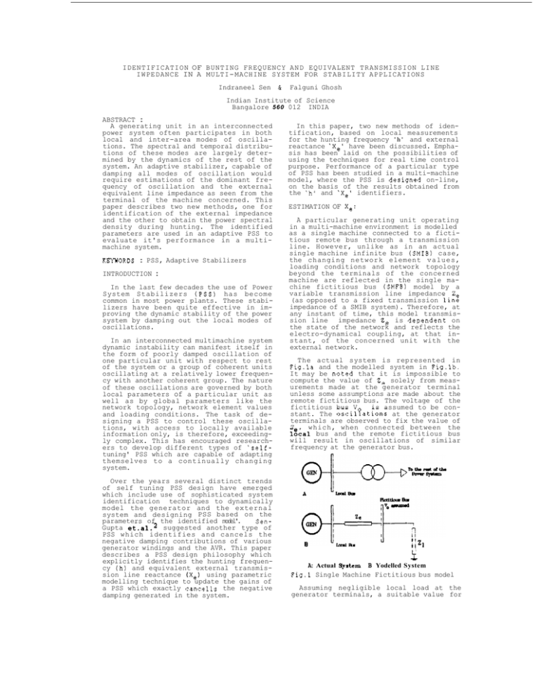
IDENTIFICATION OF BUNTING FREQUENCY AND EQUIVALENT TRANSMISSION LINE IWPEDANCE IN A MULTI-MACHINE SYSTEM FOR STABILITY APPLICATIONS Indraneel Sen C Falguni Ghosh Indian Institute of Science Bangalore 560 012 INDIA ABSTRACT : A generating unit in an interconnected power system often participates in both local and inter-area modes of oscillations. The spectral and temporal distributions of these modes are largely determined by the dynamics of the rest of the system. An adaptive stabilizer, capable of damping all modes of oscillation would require estimations of the dominant frequency of oscillation and the external equivalent line impedance as seen from the terminal of the machine concerned. This paper describes two new methods, one for identification of the external impedance and the other to obtain the power spectral density during hunting. The identified parameters are used in an adaptive PSS to evaluate it's performance in a multimachine system. KklWORDS : PSS, Adaptive Stabilizers INTRODUCTION : In the last few decades the use of Power System Stabilizers (PSS) has become common in most power plants. These stabilizers have been quite effective in improving the dynamic stability of the power system by damping out the local modes of oscillations. In an interconnected multimachine system dynamic instability can manifest itself in the form of poorly damped oscillation of one particular unit with respect to rest of the system or a group of coherent units oscillating at a relatively lower frequency with another coherent group. The nature of these oscillations are governed by both local parameters of a particular unit as well as by global parameters like the network topology, network element values and loading conditions. The task of designing a PSS to control these oscillations, with access to locally available information only, is therefore, exceedingly complex. This has encouraged researchers to develop different types of 'selftuning' PSS which are capable of adapting themselves to a continually changing system. Over the years several distinct trends of self tuning PSS design have emerged which include use of sophisticated system identification techniques to dynamically model the generator and the external system and designing PSS based on the parameters of the identified model'. SenGupta et.al.2 suggested another type of PSS which identifies and cancels the negative damping contributions of various generator windings and the AVR. This paper describes a PSS design philosophy which explicitly identifies the hunting frequency ( h ) and equivalent external transmission line reactance (Xe) using parametric modelling technique to update the gains of a PSS which exactly cancells the negative damping generated in the system. In this paper, two new methods of identification, based on local measurements for the hunting frequency ' h ' and external reactance *Xe' have been discussed. Emphasis has been laid on the possibilities of using the techniques for real time control purpose. Performance of a particular type of PSS has been studied in a multi-machine model, where the PSS is designed on-line, on the basis of the results obtained from the 'h' and 'Xe' identifiers. ESTIMATION OF Xe: A particular generating unit operating in a multi-machine environment is modelled as a single machine connected to a fictitious remote bus through a transmission line. However, unlike as in an actual single machine infinite bus (SMIB) case, the changing network element values, loading conditions and network topology beyond the terminals of the concerned machine are reflected in the single machine fictitious bus (SMFB) model by a variable transmission line impedance Z (as opposed to a fixed transmission linz impedance of a SMIB system). Therefore, at any instant of time, this model transmission line impedance Ze is dependent on the state of the network and reflects the electro-dynamical coupling, at that instant, of the concerned unit with the external network. The actual system is represented in Fig.la and the modelled system in Fig.lb. It may be noted that it is impossible to compute the value of Z, solely from measurements made at the generator terminal unless some assumptions are made about the remote fictitious bus. The voltage of the is assumed to be confictitious bus V stant. The oscilfations at the generator terminals are observed to fix the value of Z which, when connected between the lgial bus and the remote fictitious bus will result in oscillations of similar frequency at the generator bus. Ll I j z1 1 A: Actual Sprtem B Yodelled System Fig.1 Single Machine Fictitious bus model Assuming negligible local load at the generator terminals, a suitable value for
