Lecture #12 Dr. Haydar Al-Ethari Critical resolved shear stress
advertisement
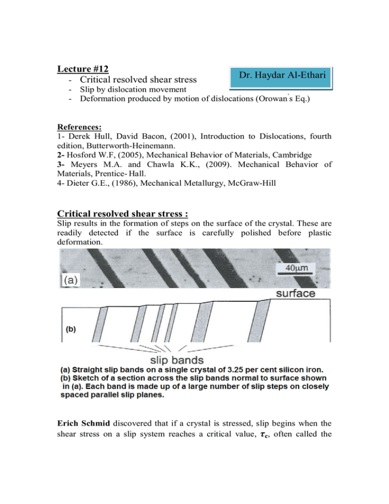
Lecture #12 - Critical resolved shear stress Dr. Haydar Al-Ethari - Slip by dislocation movement - Deformation produced by motion of dislocations (Orowan’s Eq.) References: 1- Derek Hull, David Bacon, (2001), Introduction to Dislocations, fourth edition, Butterworth-Heinemann. 2- Hosford W.F, (2005), Mechanical Behavior of Materials, Cambridge 3- Meyers M.A. and Chawla K.K., (2009). Mechanical Behavior of Materials, Prentice- Hall. 4- Dieter G.E., (1986), Mechanical Metallurgy, McGraw-Hill Critical resolved shear stress : Slip results in the formation of steps on the surface of the crystal. These are readily detected if the surface is carefully polished before plastic deformation. Erich Schmid discovered that if a crystal is stressed, slip begins when the shear stress on a slip system reaches a critical value, c, often called the critical resolved shear stress. In most crystals, slip occurs with equal ease forward or backward, so a characteristic shear stress is required for slip. Consider a crystal with a cross-sectional area A0 being deformed in tension by an applied force F along the axis of the cylindrical crystal. where cosφ cos λ is Schmid Factor. The active slip system will have the largest Schmid factor. 0 τcrss=τmax=σ/2 τ crss = 0 for for λ =ϕ =45 0 λ =ϕ =90 (N0 slip, so fracture) Example 1: A tensile stress of = 5 kPa is applied parallel to the [432] direction of a cubic crystal. Find the shear stress, , on the (11 1 ) plane in the [011] direction. SOL. First find m = cos cos for (11 1 )[011] slip. In cubic crystals, the normal to a plane has the same indices as the plane, so the normal to (11 1 ) is [11 1 ]. Also, in cubic crystals, the cosine of the angle between two directions is given by the dot product of unit vectors in those directions. Therefore cos = (4·1 + 3·1 + 2· 1 )/[(42 + 32 + 22)1/2(12 + 12 + 1 2)1/2] = 5/ ( 29 3), cos = (4·0 + 3·1 + 2·1)/[(42 + 32 + 22)1/2(02 + 12 + 12)1/2] = 5/ ( 29 2), m = cos cos = 25/(29 6) = 0.352, = = 0.352 × 5kPa = 1.76 KPa. - Impurities increase critical resolved shear stress (see Cu & Ag) - Alloying element additions (to produce a solid solution) have their effect on increasing the critical resolved shear stress (see Au & Ag). - The magnitude of the critical resolved shear stress is determined by the interaction of its dislocations with each other and with defects (as vacancies, interstitials, and impurity atoms), so critical resolved shear stress decreases as the density of defects decreases, provided that the total number of imperfections is not zero (critical resolved shear stress of soft metals can be reduced to less than one third by increasing the purity). At the other extreme, tensile tests on whiskers (dislocation-free) have given strengths which are approximately equal to the calculated strength of a perfect crystal. Slip by dislocation movement : Dislocation motion works as a deformation mechanism because relatively little atomic motion is required compared with the process of slip for perfect (defect free) crystals. Movement of an edge dislocation: the arrows indicate the applied shear stress. When the extra half plane of atoms reaches a free surface, it results in a slip step of one Burgers vector or one atomic distance for the simple cubic lattice. The applied stress required to overcome the lattice resistance to the movement of the dislocation is the Peierls-Nabarro stress. It is the applied resolved shear stress required to make a dislocation glide in an otherwise perfect crystal. It arises as a direct consequence of the periodic structure of the crystal lattice and depends sensitively on the form of the force-distance relation between individual atoms, i.e. on the nature of the interatomic bonding. It is a function of the core structure and, for this reason; a unique analytical expression for the Peierls stress cannot be derived. τ P − N = 2G (1 − υ − 2π w exp ) b ≈ 2G (1 − υ − 2π a exp ) (1 − υ )b When: w- width of dislocation; a- distance between slip planes and bdistance between atoms in the slip direction. τ P−N vary with crystal structure. In general τ P− N << τ theoretical The Peierls stress is very sensitive to the atomic position at the core of dislocation (affected by the width in the equation above), and as the positions are not known with a high degree of accuracy the equation cannot be used for precise calculation. The equation is accurate enough to show that the stresses needed to move the dislocation in a metal is quite low. Wide dislocation ⇒ low stress to move it ( as in ductile metals) Narrow dislocation ⇒ high stress to move it (as in ceramics). Deformation produced by motion of dislocations (Orowan’s Eq.) (a)- If a single dislocation passes through a cubic crystal, the resulting strain: Shear strain, = b/h With N dibslocations, = N.b/h this expression assumes that all dislocations pass all of the way through the crystal. In reality we can not make that assumption. Thus we need to revise our estimate. (b)- When dislocations pass partially through a crystal: Assuming that all of the dislocations move a distance x i along the crystal length, the strain equations will be: So : - single dislocation: γ = - multiple dislocation: x ib Lh b γ = Lh N ∑x If N dislocations move an average distance x γ = i i then, Nxb Lh L ∗ h = area of the end of the crystal Dislocation density = ρ ⊥ = ρ⊥ # ⊥ lines N = Lh area ∴γ = ρ⊥bx - The total dislocation line length per unit volume or the number of dislocation lines that cut a unit cross-sectional area. The shear strain rate associated with this type of motion is: • γ= dγ dx = ρ⊥b = ρ⊥bv dt dt Where: v is the dislocation velocity. This equation is the Taylor- Orowan relation, which relates dislocation motion to strain rate.
