6.8 AXIAL FLOW PUMP
advertisement

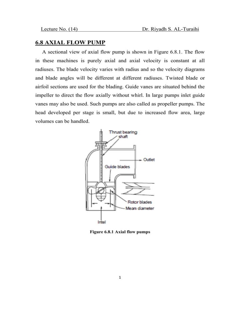
Lecture No. (14) Dr. Riyadh S. AL-Turaihi 6.8 AXIAL FLOW PUMP A sectional view of axial flow pump is shown in Figure 6.8.1. The flow in these machines is purely axial and axial velocity is constant at all radiuses. The blade velocity varies with radius and so the velocity diagrams and blade angles will be different at different radiuses. Twisted blade or airfoil sections are used for the blading. Guide vanes are situated behind the impeller to direct the flow axially without whirl. In large pumps inlet guide vanes may also be used. Such pumps are also called as propeller pumps. The head developed per stage is small, but due to increased flow area, large volumes can be handled. Figure 6.8.1 Axial flow pumps 1 Lecture No. (14) Dr. Riyadh S. AL-Turaihi A comparison of values of parameters is given in table 6.8.1. Table 6.8.1 Comparative values of parameter for different types of pumps The whirl at inlet is zero. The velocity triangles are given in Figure 6.8.2.Va is constant at all sections both at inlet and outlet. u varies with radius. Hence β1 and β2 will vary with radius. as in the case of centrifugal pumps. All other efficiencies are similar to the centrifugal pump. The angle turned by the fluid during the flow over the blades is about 10 – 15°. Hence whirl imparted per stage is small. The number of blades is limited as in the case of Kaplan turbine ranging between 2 and 8. The hub to tip ratio is in the range 0.3 to 0.6. Generally the blades are fixed. In rare designs the blades are rotated as in the case of Kaplan turbine by suitable governing mechanism. 2 Lecture No. (14) Dr. Riyadh S. AL-Turaihi Figure 6.8.2 Velocity triangles axial pump 6.9 POWER TRANSMITTING SYSTEMS Ordinarily power is transmitted by mechanical means like gear drive or belt drive. In the case of gear drive there is a rigid connection between the driving and driven shafts. The shocks and vibrations are passed on from one side to the other which is not desirable. Also gear drives cannot provide a stepless variation of speeds. In certain cases where the driven machine has a large inertia, the driving prime mover like electric motor will not be able to provide a large starting torque. Instead of the mechanical connection if fluids can be used for such drives, high inertia can be met. Also shock loads and vibration will not be passed on. Smooth speed variation is also possible. The power transmitting systems offer these advantages. There are two types power transmitting devices. These are : (i) Fluid coupling (ii) Torque converter or torque multiplier. 3 Lecture No. (14) Dr. Riyadh S. AL-Turaihi 6.9.1 Fluid Coupling A sectional view of a fluid coupling is shown in figure 6.9.1. Figure 6.9.1 Fluid coupling In this device the driving and driven shafts are not rigidly connected. The drive shaft carries a pump with radial vanes and the driven shaft carries a turbine runner. Both of these are enclosed in a casing filled with oil of suitable viscosity. The pump accelerates the oil by imparting energy to it. The oil is directed suitably to hit the turbine vanes where the energy is absorbed and the oil is decelerated. The decelerated oil now enters the pump and the cycle is repeated. There is no flow of fluid to or from the outside. The oil transfers the energy from the drive shaft to the driven shaft. As there is no mechanical connection between the shafts, stock loads or vibration will not be passed on from one to the other. The turbine will start rotating only after a certain level of energy picked up by the oil from the pump. Thus the prime mover can pick up speed with lower starting torque before the power is transmitted. In this way heavy devices like power plant blowers can be 4 Lecture No. (14) Dr. Riyadh S. AL-Turaihi started with motors with lower starting torque. The pump and turbine can not rotate at the same speeds. In case these do run at the same speed, there can be no circulation of oil between them as the centrifugal heads of the pump and turbine are equal, and no energy will be transferred from one to the other. The ratio of difference in speeds to the driver speed is known as slips, S. where ωp is the pump speed and ωT is the turbine speed. The variation of slip with pump speed is shown in figure 6.9.2.As shown up to the pump speed ωps the turbine will not run and slip is 100%. As the driver speed increases slip rapidly decreases and at the operating conditions reaches values of about 2 to 5%. Figure 6.9.2 Slip variation with pump speed 5 Lecture No. (14) Dr. Riyadh S. AL-Turaihi The efficiency of transmission 6


