Refrigeration Cycle Problem: R-134a Analysis & COP Calculation
11-7
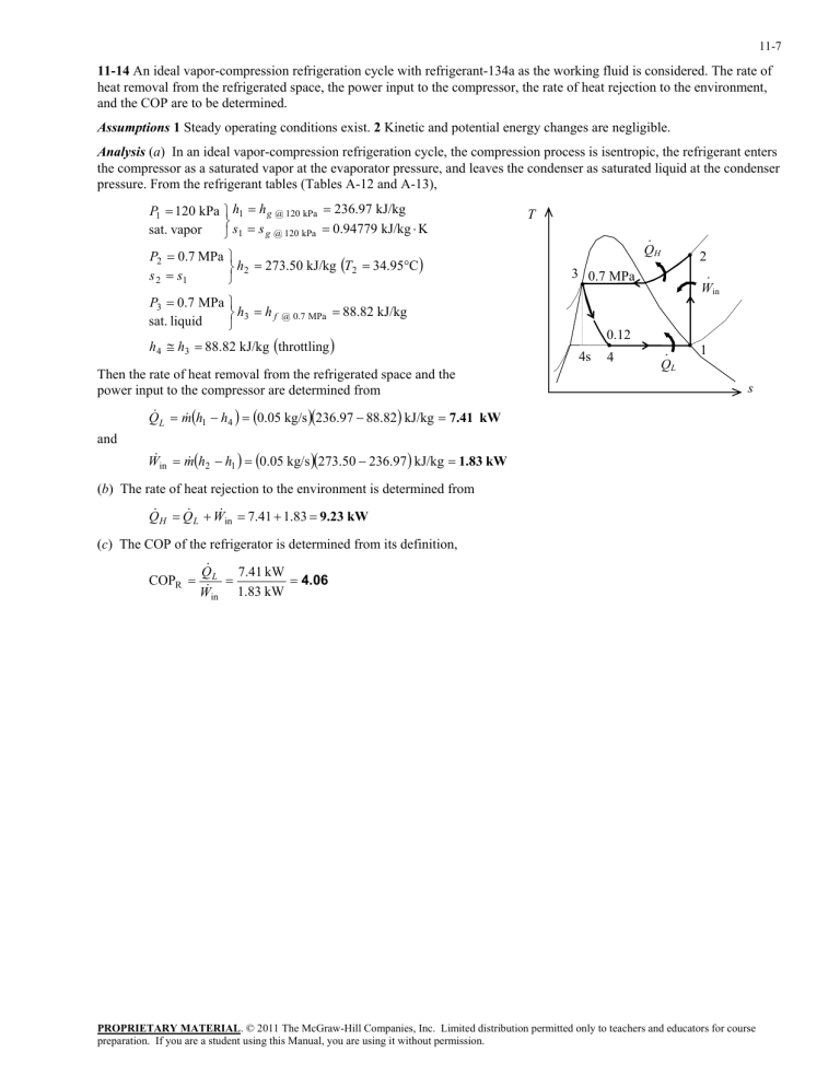
11-14 An ideal vapor-compression refrigeration cycle with refrigerant-134a as the working fluid is considered. The rate of heat removal from the refrigerated space, the power input to the compressor, the rate of heat rejection to the environment, and the COP are to be determined.
Assumptions 1 Steady operating conditions exist. 2 Kinetic and potential energy changes are negligible.
Analysis ( a ) In an ideal vapor-compression refrigeration cycle, the compression process is isentropic, the refrigerant enters the compressor as a saturated vapor at the evaporator pressure, and leaves the condenser as saturated liquid at the condenser pressure. From the refrigerant tables (Tables A-12 and A-13),
P
1
120 sat.
vapor kPa h
1 s
1
h g @ 120 kPa s g @ 120 kPa
236 .
97 kJ/kg
0 .
94779 kJ/kg
K
T
·
Q
H 2 P
2 s
2
0 .
7 MPa s
1 h
2
273 .
50 kJ/kg
T
2
34 .
95
C
P
3
0 .
7 sat.
liquid
MPa h
4
h
3 h
3
h f @ 0 .
7 MPa
88 .
82 kJ/kg
throttling
88 .
82 kJ/kg
3 0.7 MPa
4s
0.12
4 ·
Q
L
·
W in
1
Then the rate of heat removal from the refrigerated space and the power input to the compressor are determined from
L
h
1
h
4
0.05
kg/s
236 .
97
88 .
82
kJ/kg
7.41
kW and
in
h
2
h
1
0.05
kg/s
273.50
236.97
kJ/kg
1.83
kW s
( b ) The rate of heat rejection to the environment is determined from
H
L
in
7 .
41
1 .
83
9.23
kW
( c ) The COP of the refrigerator is determined from its definition,
COP
R
L
in
7.41
kW
1.83
kW
4.06
PROPRIETARY MATERIAL . © 2011 The McGraw-Hill Companies, Inc. Limited distribution permitted only to teachers and educators for course preparation. If you are a student using this Manual, you are using it without permission.
