Vapor-Compression Refrigeration Cycle Tutorial
advertisement
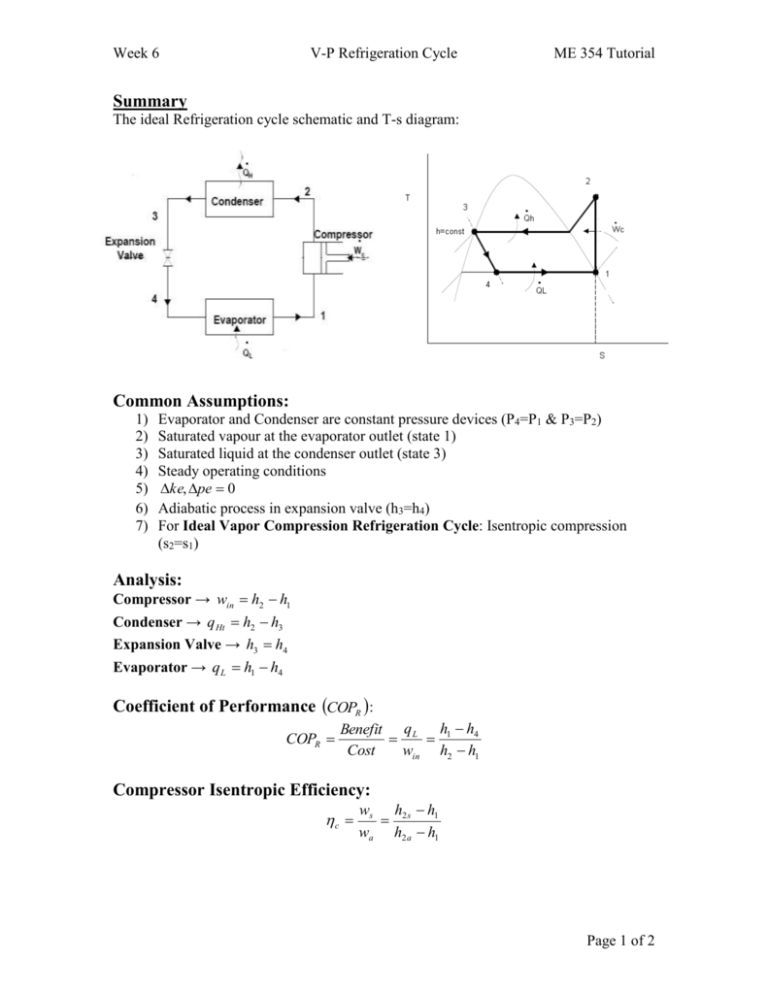
Week 6 V-P Refrigeration Cycle ME 354 Tutorial Summary The ideal Refrigeration cycle schematic and T-s diagram: Common Assumptions: 1) 2) 3) 4) 5) 6) 7) Evaporator and Condenser are constant pressure devices (P4=P1 & P3=P2) Saturated vapour at the evaporator outlet (state 1) Saturated liquid at the condenser outlet (state 3) Steady operating conditions ke, pe 0 Adiabatic process in expansion valve (h3=h4) For Ideal Vapor Compression Refrigeration Cycle: Isentropic compression (s2=s1) Analysis: Compressor → win h2 h1 Condenser → q Ht h2 h3 Expansion Valve → h3 h4 Evaporator → qL h1 h4 Coefficient of Performance COPR : COPR Benefit q L h1 h4 Cost win h2 h1 Compressor Isentropic Efficiency: c ws h2 s h1 wa h2 a h1 Page 1 of 2 Week 6 V-P Refrigeration Cycle ME 354 Tutorial Question A large refrigeration plant is to be maintained at -15oC, and it requires refrigeration at a rate of 100 kW. The condenser of the plant is to be cooled by liquid water, which experiences a temperature rise of 8oC as it flows over the coils of the condenser. The plant uses refrigerant-134a between the pressure limits of 120 kPa and 700 kPa. Assuming the compressor has an isentropic efficiency of 75%, determine: a) The mass flow rate of the refrigerant b) The power input to the compressor c) The mass flow rate of the cooling water d) The rate of exergy destruction associated with the compression process (assume T0=25oC) Page 2 of 2
