cooling, the power input, and the COP are to be... 11-26
advertisement
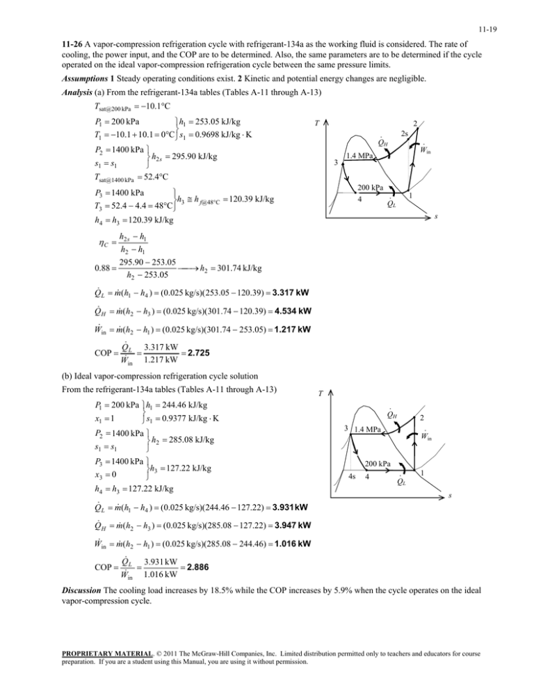
11-19 11-26 A vapor-compression refrigeration cycle with refrigerant-134a as the working fluid is considered. The rate of cooling, the power input, and the COP are to be determined. Also, the same parameters are to be determined if the cycle operated on the ideal vapor-compression refrigeration cycle between the same pressure limits. Assumptions 1 Steady operating conditions exist. 2 Kinetic and potential energy changes are negligible. Analysis (a) From the refrigerant-134a tables (Tables A-11 through A-13) Tsat@200 kPa 10.1C P1 200 kPa h1 253.05 kJ/kg T1 10.1 10.1 0C s1 0.9698 kJ/kg K T 2 · QH P2 1400 kPa h2 s 295.90 kJ/kg s1 s1 Tsat@1400 kPa 52.4C 3 200 kPa h3 h f@48C 120.39 kJ/kg T3 52.4 4.4 48C h4 h3 120.39 kJ/kg 0.88 · Win 1.4 MPa P3 1400 kPa C 2s 1 · QL 4 s h2 s h1 h2 h1 295.90 253.05 h2 301.74 kJ/kg h2 253.05 Q L m (h1 h4 ) (0.025 kg/s)( 253.05 120.39) 3.317 kW Q H m (h2 h3 ) (0.025 kg/s)(301.74 120.39) 4.534 kW W in m (h2 h1 ) (0.025 kg/s)(301.74 253.05) 1.217 kW COP Q L 3.317 kW 2.725 W in 1.217 kW (b) Ideal vapor-compression refrigeration cycle solution From the refrigerant-134a tables (Tables A-11 through A-13) P1 200 kPa h1 244.46 kJ/kg x1 1 s1 0.9377 kJ/kg K P2 1400 kPa h2 285.08 kJ/kg s1 s1 P3 1400 kPa h3 127.22 kJ/kg x3 0 h4 h3 127.22 kJ/kg T · QH 2 3 1.4 MPa · Win 200 kPa 4s 4 · QL 1 s Q L m (h1 h4 ) (0.025 kg/s)(244.46 127.22) 3.931 kW Q H m (h2 h3 ) (0.025 kg/s)(285.08 127.22) 3.947 kW W in m (h2 h1 ) (0.025 kg/s)(285.08 244.46) 1.016 kW COP Q L 3.931 kW 2.886 W in 1.016 kW Discussion The cooling load increases by 18.5% while the COP increases by 5.9% when the cycle operates on the ideal vapor-compression cycle. PROPRIETARY MATERIAL. © 2011 The McGraw-Hill Companies, Inc. Limited distribution permitted only to teachers and educators for course preparation. If you are a student using this Manual, you are using it without permission.

