How Ultrasound
advertisement
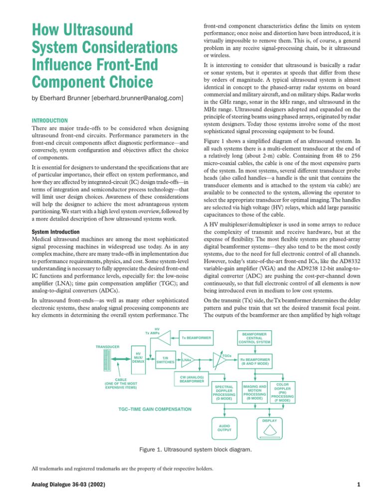
How Ultrasound System Considerations Influence Front-End Component Choice front-end component characteristics define the limits on system performance; once noise and distortion have been introduced, it is virtually impossible to remove them. This is, of course, a general problem in any receive signal-processing chain, be it ultrasound or wireless. by Eberhard Brunner [eberhard.brunner@analog.com] INTRODUCTION There are major trade-offs to be considered when designing ultrasound front-end circuits. Performance parameters in the front-end circuit components affect diagnostic performance—and conversely, system configuration and objectives affect the choice of components. It is essential for designers to understand the specifications that are of particular importance, their effect on system performance, and how they are affected by integrated-circuit (IC) design trade-offs—in terms of integration and semiconductor process technology—that will limit user design choices. Awareness of these considerations will help the designer to achieve the most advantageous system partitioning. We start with a high level system overview, followed by a more detailed description of how ultrasound systems work. It is interesting to consider that ultrasound is basically a radar or sonar system, but it operates at speeds that differ from these by orders of magnitude. A typical ultrasound system is almost identical in concept to the phased-array radar systems on board commercial and military aircraft, and on military ships. Radar works in the GHz range, sonar in the kHz range, and ultrasound in the MHz range. Ultrasound designers adopted and expanded on the principle of steering beams using phased arrays, originated by radar system designers. Today those systems involve some of the most sophisticated signal processing equipment to be found. Figure 1 shows a simplified diagram of an ultrasound system. In all such systems there is a multi-element transducer at the end of a relatively long (about 2-m) cable. Containing from 48 to 256 micro-coaxial cables, the cable is one of the most expensive parts of the system. In most systems, several different transducer probe heads (also called handles—a handle is the unit that contains the transducer elements and is attached to the system via cable) are available to be connected to the system, allowing the operator to select the appropriate transducer for optimal imaging. The handles are selected via high voltage (HV) relays, which add large parasitic capacitances to those of the cable. Medical ultrasound machines are among the most sophisticated signal processing machines in widespread use today. As in any complex machine, there are many trade-offs in implementation due to performance requirements, physics, and cost. Some system-level understanding is necessary to fully appreciate the desired front-end IC functions and performance levels, especially for: the low-noise amplifier (LNA); time gain compensation amplifier (TGC); and analog-to-digital converters (ADCs). A HV multiplexer/demultiplexer is used in some arrays to reduce the complexity of transmit and receive hardware, but at the expense of flexibility. The most flexible systems are phased-array digital beamformer systems—they also tend to be the most costly systems, due to the need for full electronic control of all channels. However, today’s state-of-the-art front-end ICs, like the AD8332 variable-gain amplifier (VGA) and the AD9238 12-bit analog-todigital converter (ADC) are pushing the cost-per-channel down continuously, so that full electronic control of all elements is now being introduced even in medium to low cost systems. In ultrasound front-ends—as well as many other sophisticated electronic systems, these analog signal processing components are key elements in determining the overall system performance. The On the transmit (Tx) side, the Tx beamformer determines the delay pattern and pulse train that set the desired transmit focal point. The outputs of the beamformer are then amplified by high voltage System Introduction HV Tx AMPs BEAMFORMER CENTRAL CONTROL SYSTEM Tx BEAMFORMER TRANSDUCER HV MUX/ DEMUX CABLE (ONE OF THE MOST EXPENSIVE ITEMS) T/R SWITCHES TGCs LNAs Rx BEAMFORMER (B AND F MODE) CW (ANALOG) BEAMFORMER SPECTRAL DOPPLER PROCESSING (D MODE) IMAGING AND MOTION PROCESSING (B MODE) COLOR DOPPLER (PW) PROCESSING (F MODE) TGC–TIME GAIN COMPENSATION DISPLAY AUDIO OUTPUT Figure 1. Ultrasound system block diagram. All trademarks and registered trademarks are the property of their respective holders. Analog Dialogue 36-03 (2002) 1 transmit amplifiers that drive the transducers.These amplifiers might be controlled by digital-to-analog converters (DACs) to shape the transmit pulses for better energy delivery to the transducer elements. Typically, multiple transmit focal regions (zones) are used—that is, the field to be imaged is deepened by focusing the transmit energy at progressively deeper points in the body. The main reason for multiple zones is that the transmit energy needs to be greater for points that are deeper in the body, because of the signal’s attenuation as it travels into the body (and as it returns). On the receive (Rx) side, there is a T/R switch, generally a diode bridge, which blocks the high voltage Tx pulses. It is followed by a low-noise amplifier (LNA) and one or more variable-gain amplifiers (VGAs), which implement time gain compensation (TGC) and sometimes also apodization (spatial “windowing” to reduce sidelobes in beam) functions. Time gain control—which provides increased gain for signals from deeper in the body (and therefore arriving later)—is under operator control and used to maintain image uniformity. After amplification, beamforming is performed, implemented in either analog (ABF) or digital (DBF) form. It is mostly digital in modern systems, except for continuous-wave (CW) Doppler processing, whose dynamic range is still too large to be processed through the same channel as the image. Finally, the Rx beams are processed to show either a gray-scale image, Colorflow overlay on the 2-D image, and/or a Doppler output. Ultrasound System Challenges To fully understand the challenges in ultrasound and their impact on the front-end components, it is important to remember what this imaging modality is trying to achieve. First, it is supposed to give an accurate representation of the internal organs of a human body, and second, through Doppler signal processing, it is to determine movement within the body (for example, blood flow). From this information a doctor can then make conclusions about the correct functioning of a heart valve or blood vessel. Acquisition Modes There are three main ultrasonic acquisition modes: B-mode (grayscale imaging; 2D); F-mode (Colorflow or Doppler Imaging; blood flow); and D-mode (Spectral Doppler). B-mode creates the traditional gray-scale image; F-mode is a color overlay on the B-mode display that shows blood flow; D-mode is the Doppler display that might show blood flow velocities and their frequencies. (There is also an M-mode, which displays a single B-mode time line.) Operating frequencies for medical ultrasound are in the 1-MHz to 40-MHz range, with external imaging machines typically using frequencies of 1 MHz to 15 MHz, while intravenous cardiovascular machines use frequencies as high as 40 MHz. Higher frequencies are in principle more desirable, since they provide higher resolution— but tissue attenuation limits how high the frequency can be for a given penetration distance. However, one cannot arbitrarily increase the ultrasound frequency to get finer resolution, since the signal experiences an attenuation of about 1 dB/cm/MHz; i.e., for a 10MHz ultrasound signal and a penetration depth of 5 cm, the roundtrip signal has been attenuated by 5 2 10 = 100 dB! To handle an instantaneous dynamic range of about 60 dB at any location, the required dynamic range would be 160 dB (a voltage dynamic range of 100 million to 1)! Dynamic ranges of this magnitude are not directly achievable; therefore one has to pay the costs of a highly sophisticated system and trade off something at the front end—either 2 penetration depth (limited by safety regulations due to maximum transmit power that is allowed) or image resolution (using a lower ultrasound frequency). The large dynamic range of the received signals presents the most severe challenge. The front-end circuitry must have very low noise and large-signal handling capability simultaneously—requirements familiar to anyone experienced in the demands of communications. Cable mismatch and loss directly add to the noise figure of the system. For example, if the loss of the cable at a particular frequency is 2 dB, then the NF is degraded by 2 dB. This means that the first amplifier after the cable will have to have a noise figure that is 2 dB lower than that needed with a lossless cable. One potential way to get around this problem is to situate an amplifier in the transducer handle. However, there are serious size and power constraints; also, the need for protection from high voltage transmit pulses makes such a solution difficult to implement. Another challenge is the large acoustic impedance mismatch between the transducer elements and the body. The acoustic impedance mismatch requires matching layers (analogous to electrical-impedance-matching RF circuitry) to transmit energy efficiently. This normally consists of a couple of matching layers in front of the transducer elements in the handle, followed by a lens, followed by coupling gel. The gel establishes good acoustic contact with the body—since air is a very good acoustic reflector. Another important issue for the receive circuitry is fast overload recovery. Even though the T/R switch is supposed to protect the receiver from large pulses, a small fraction of these pulses leaking across the switches can be sufficient to overload the front-end circuitry. Poor overload recovery will make the receiver “blind” until it recovers, with a direct impact on how close to the surface of the skin an image can be generated. How an Ultrasound Image is Generated—B-Mode Figure 2 shows how the different scan images are generated. In all four scans, the pictures with the scan lines bounded by a rectangle are an actual representation of the image, as it will be seen on the display monitor. Mechanical motion of a single transducer (in the directions indicated by the arrows) is shown here to facilitate understanding of the image generation; but the same kinds of images can be generated by a linear array without mechanical motion. In the example of a linear scan, the transducer element is moved in a horizontal direction; for every scan line (the lines shown in the images), a Tx pulse is sent and the reflected signals from different depths are recorded and scan-converted to be shown on a video display. How the single transducer is moved during image acquisition determines the shape of the image. This directly translates into the shape of a linear array transducer, i.e., for the linear scan, the array would be straight, while for the arc scan, the array would be concave. The step that is needed to go from a mechanical single transducer system to an electronic system can also be easily explained by examining the linear scan in Figure 2. If the single transducer element is divided into many small pieces, then if one excites one element at a time and records the reflections from the body, one also gets the rectangular image as shown, only now one does not need to move the transducer elements. From this one can see that the arc scan can be made of a linear array that has a concave shape; and the sector scan would be made of a linear array that has a convex shape. Analog Dialogue 36-03 (2002) ITEM TO BE IMAGED LINEAR SCAN SECTOR SCAN ARC SCAN COMPOUND LINEAR SCAN IMAGE AS SEEN ON DISPLAY Figure 2. Single-transducer image generation. Even though the example above explains the basics for B-mode ultrasound image generation, in a modern system more than one element at a time is used to generate a scan line because it allows the aperture of the system to be changed. Changing the aperture is like changing the location of the focal point in optics—it helps create clearer images. Figure 3 shows how this is done for a linear array and a phased array; the main difference is that in a phased array all elements are used simultaneously, while in a linear array only a subset of the total array elements is used. Using a smaller number of elements has the advantage of saving electronic hardware; but it increases the time to image a given field of view. A phased array is different; because of its pie shape a very small transducer can image a large area in the far field. That is why phased array transducers are the transducers of choice in applications like cardiac imaging where one has to deal with the small spaces between the ribs through which the much larger heart needs to be imaged. PULSING PATTERNS TIME BODY COUPLING GEL TIME BODY IMAGE SHAPE Figure 3. Linear vs. phased-array imaging. FOCAL POINT ARRAY Excitation in arrays is directed along scan lines, determined by the delay profile of a set of pulses intended to arrive simultaneously at a focal point. The pulses (Figure 3) are represented by the “squiggles” on the vertical time lines above the array (shaded color)—with time increasing vertically from the array surface. The linear stepped array, in Figure 3, will deliver shaped excitation to a group of elements (aperture), then step the aperture by adding a leading element and dropping a trailing one. On each step one scan line (beam) is formed by the simultaneous arrival of the pulses. In the phased array, all transducers are active at the same time. In the examples shown, the darkened lines are the scan lines imaging the reflection data produced by the representative pulsing patterns. Analog vs. Digital Beamforming In analog beamforming (ABF) and digital beamforming (DBF) ultrasound systems, the received pulses reflected from a particular focal point along a beam are stored for each channel, then aligned in time, and coherently summed—this provides spatial processing gain because the noise of the channels is uncorrelated. Images may be formed as either a sequence of analog levels that are delayed with analog delay lines, summed, and converted to digital after summation (ABF)—or digitally by sampling the analog levels as close as possible to the transducer elements, storing them in a memory (FIFO), and then summing them digitally (DBF). Figures 4 and 5 show basic respective block diagrams of ABF and DBF systems. Both types of systems require perfect channel-tochannel matching. Note that the variable-gain amplifiers (VGAs) are needed in both implementations—and will continue to be in the digital case until ADCs with a large enough dynamic range become available at reasonable cost and low enough power. Note that an VARIABLE DELAYS OUTPUT SIGNAL ANALOG ADDER ADC Figure 4. Simplified block diagram of ABF system. Analog Dialogue 36-03 (2002) 3 FOCAL POINT VARIABLE DELAYS ARRAY ADC FIFO ADC FIFO ADC FIFO ADC FIFO ADC FIFO ADC FIFO ADC FIFO DIGITAL ADDER OUTPUT SIGNAL SAMPLING CLOCK Figure 5. Simplified block diagram of DBF system. ABF imaging system needs only one very high resolution and high speed ADC, but a DBF system requires many high speed, high resolution ADCs. Sometimes a logarithmic amplifier is used in the ABF systems to compress the dynamic range before the ADC. processing in Figure 1.The ABF has larger dynamic range. Naturally, the “Holy Grail” in DBF ultrasound is for all modes to be processed through the DBF chain (at realistic cost), and there is a great deal of ongoing research as to how to get there. Dynamic Range Power In the front-end circuitry, the noise floor of the LNA determines how weak a signal can be received. But at the same time—especially during CW Doppler signal processing—the LNA must also be able to handle very large signals. So it is crucial to maximize the dynamic range of the LNA (in general, it is impossible to implement any filtering before the LNA due to noise constraints). Note that these same conditions apply for any receiver—in communications applications, the circuitry closest to the antenna does not have the advantage of a lot of filtering either; accordingly, it needs to cope with the largest dynamic range. Since ultrasound systems require many channels, power consumption of all the front-end components—from T/R switch, through LNA, VGA, and ADC, to the digital circuitry of the beamformer—is a very critical specification. As has been pointed out above, there will always be a push to increase the front-end dynamic range in order to arrive at eventual integration of all ultrasound modes into one beamformer—a tendency that will lead towards increasing the power in the system. However, there is a corresponding need to make the ultrasound systems forever smaller—with a tendency towards reducing power. Power in digital circuits usually decreases with supply voltage; but this is not necessarily true for analog and mixed signal circuitry. Furthermore, taking into account the fact that reduced analog “headroom” tends to reduce dynamic range, there will be a limit to how low the supply voltage can go and still achieve a desired dynamic range. CW Doppler has the largest dynamic range of all signals in an ultrasound system—during CW, a sine wave is transmitted continuously with half of the transducer array, while the other half is receiving. There is a strong tendency for the Tx signal to leak into the Rx side; and there are also strong reflections coming from stationary body parts that are close to the surface. This tends to interfere with examination of, for example, blood flow in a vein deep in the body with concomitant very weak Doppler signals. At the current state of the art, CW Doppler signals cannot be processed through the main imaging (B-mode) and PW Doppler (F-mode) path in a digital beamforming (DBF) system; for this reason, an analog beamformer (ABF) is indicated for CW Doppler CONCLUSION We have sought to show here the trade-offs required in front-end ICs for ultrasound by explaining the basic operation of such a system first, and then pointing out what particular performance parameters are needed to ensure optimal system operation. A more complete version of this paper1 is available to provide additional details. b 1 Brunner, Eberhard, “Ultrasound System Considerations and their Impact on Front-End Components,” Analog Devices, Inc., 2002 (http://www.analog.com/ library/analogDialogue/archives/36-03/ultrasound/UltrasoundFrontend.pdf). 4 Analog Dialogue 36-03 (2002)


![Jiye Jin-2014[1].3.17](http://s2.studylib.net/store/data/005485437_1-38483f116d2f44a767f9ba4fa894c894-300x300.png)
